12/30/2026
Over the years, I've made many little doohickeys and gizmos that I never bothered to write about. There's a bunch more, but here's all of them I could find. I tried my best to timestamp these but they're not in any particular order. Please let me know if you would like to hear more about them!!! Never a chore to write about the things I love the most.
TIME MACHINE MK. ][
Early 2018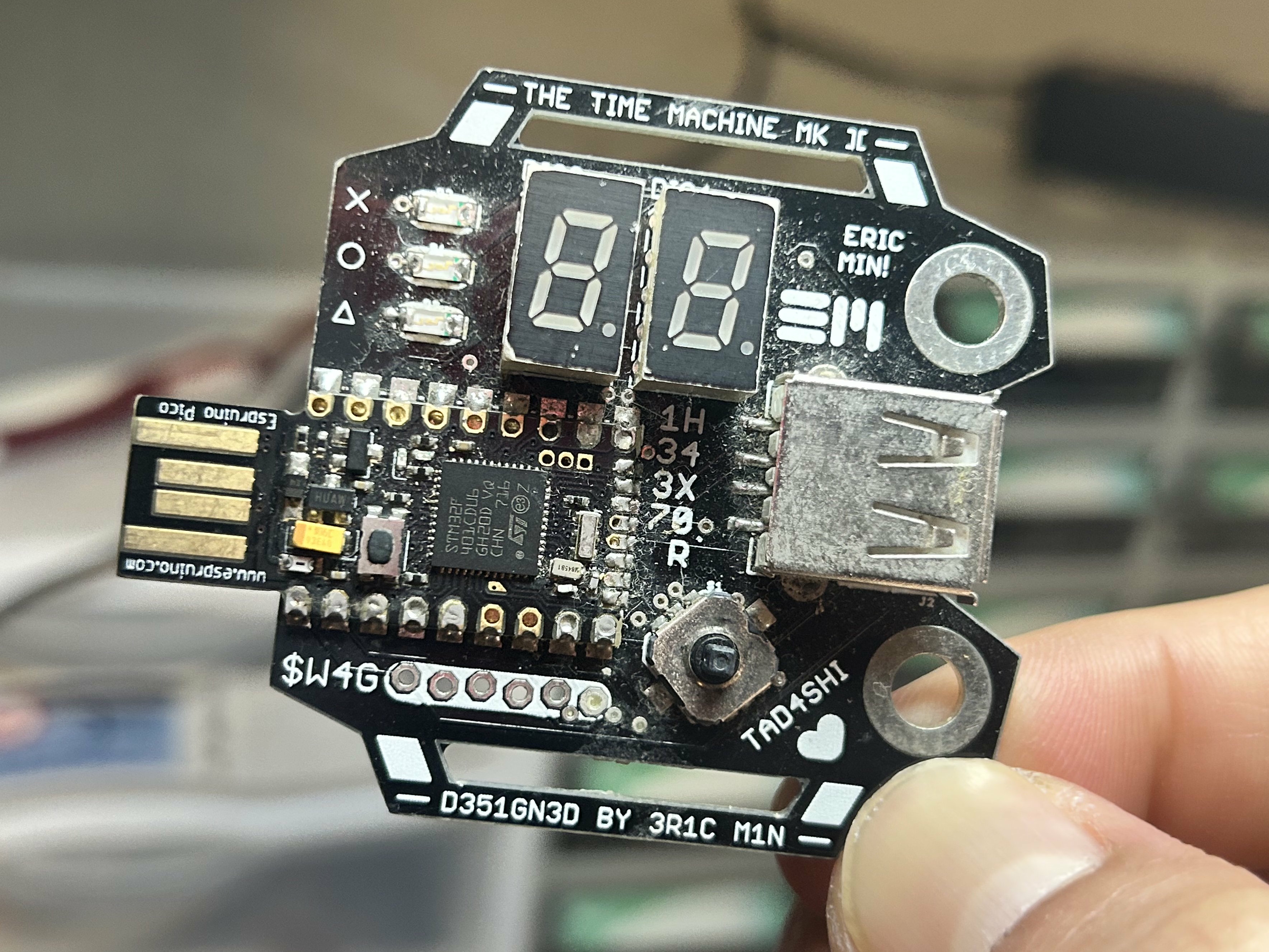
My first Time Machine! I started with two because I didn't want to start with one. It uses an Espruino Pico module for its brains, and I wrote the Javascript code that runs on top of the Espruino firmware. This was way back when I was a sophomore in high school and had no idea how to code in C, but still a confusing choice nonetheless looking back at it now.
I was too lazy to write anything more than what I was happy with, which really wasn't much at the time. I was too lazy to even write code to handle minutes properly, so I had it display minutes in counts of five. So it would only display the time in intervals of five minutes. The oscillator on the Espruino Pico was also far from accurate, so there was significant drifting, and the time was rarely ever accurate. Still, I loved this thing, because it was mine. Mine as in I made it all by myself.
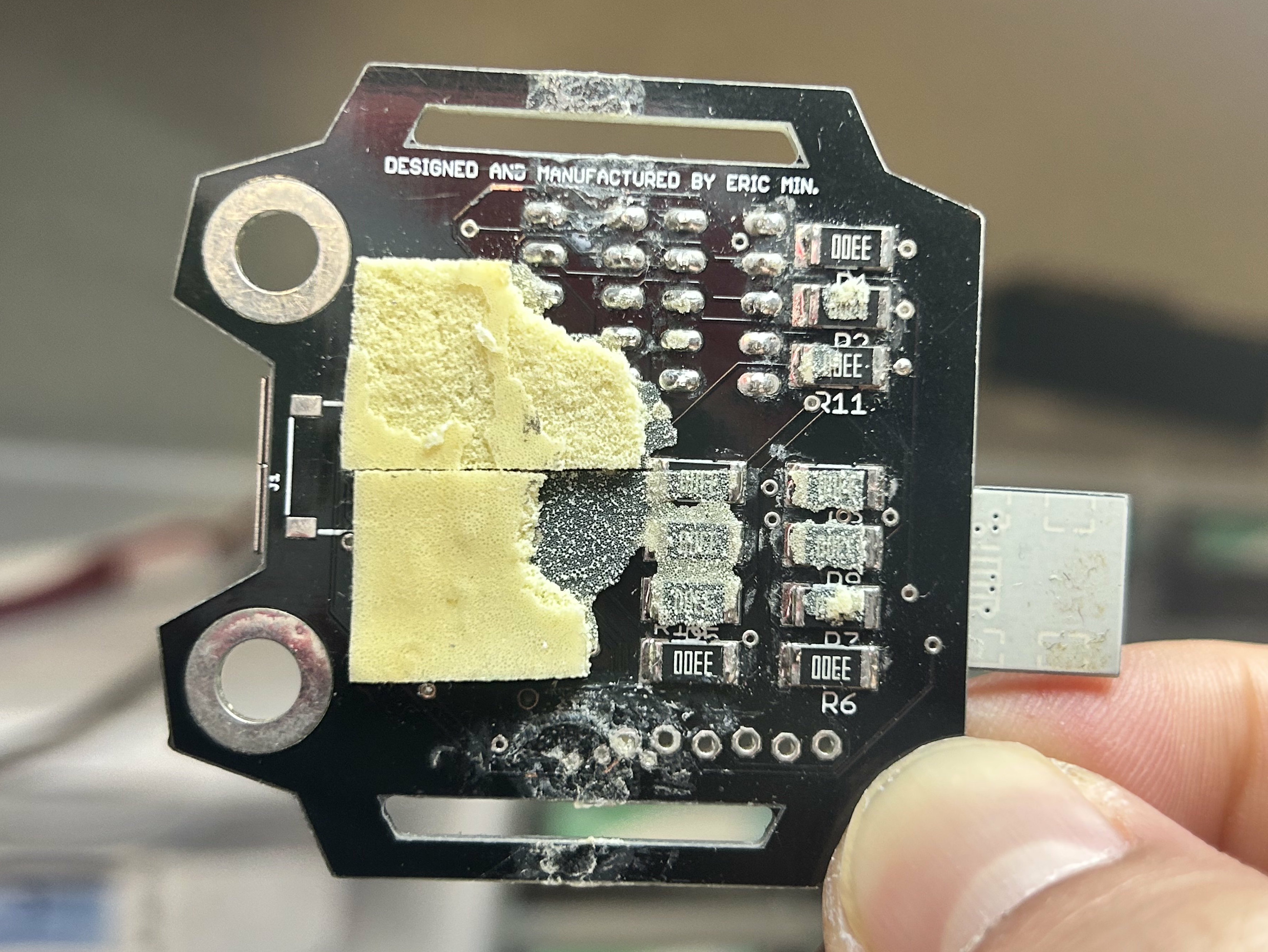
Battery modules would stick into the USB port like this,
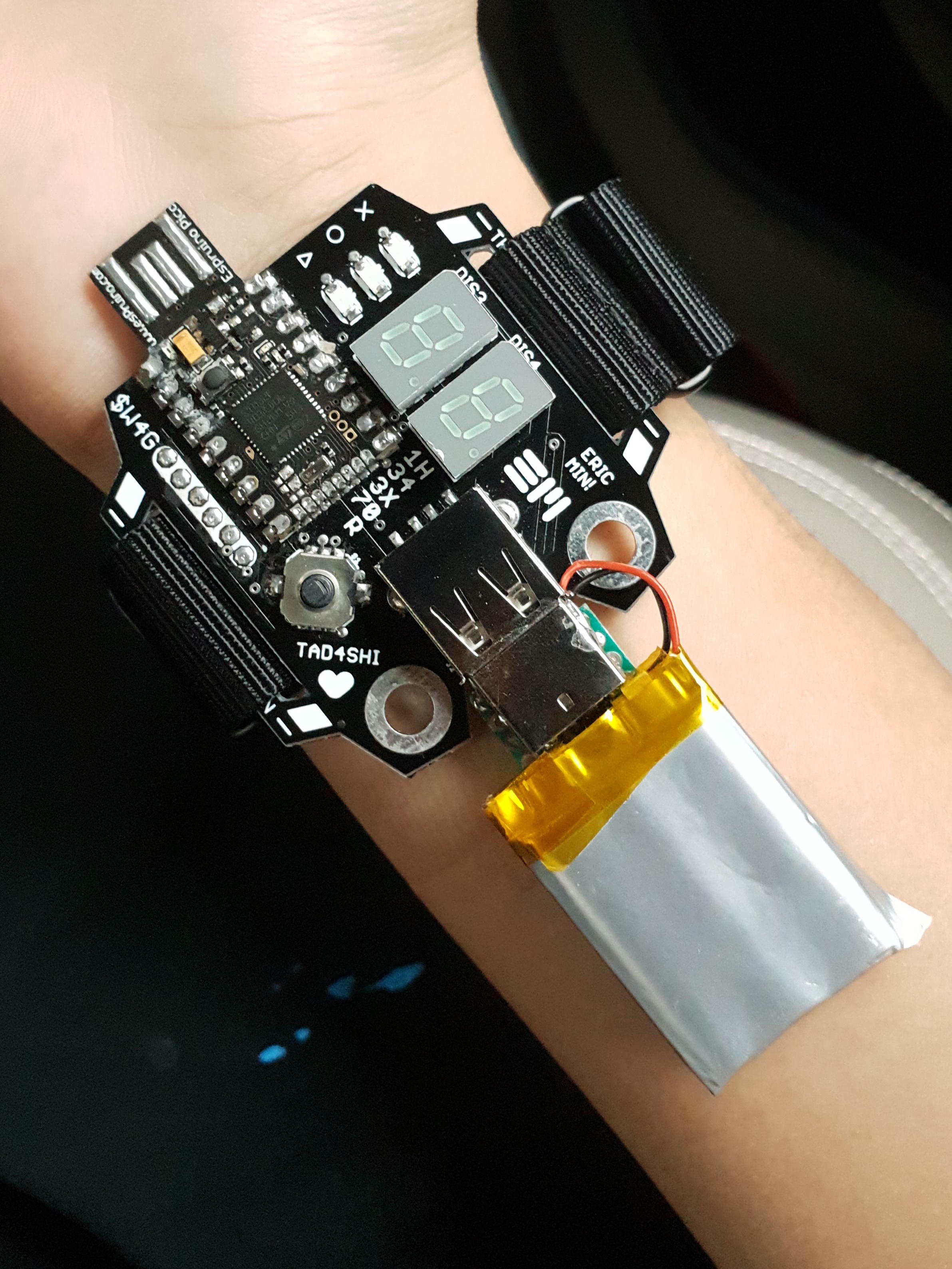
which was inspired by Spider Man's web shooters. I actually used to go around wearing this with the battery and everything, both in school and out. I'm sure I looked ridiculous. Eventually, I got tired of the battery stick and just stuck a lipo on the back of the board (hence the sticky tape residue) and soldered a USB-A male plug on the battery wires, connecting it to the watch.
Still, I think it was a pretty cool project. You can definitely see parts of the design that carried over to subsequent Time Machine models.
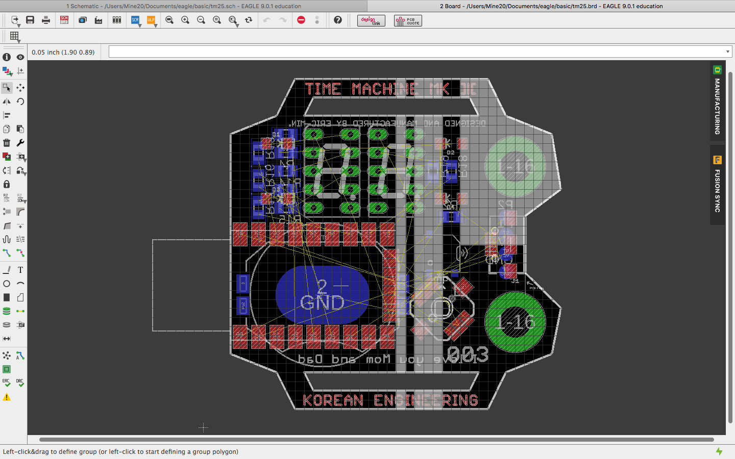
Here is a concept design I found for Time Machine Mk. 3 and an one for Mk. 4. You can see TM3 was going to be an evolution of TM2, with a new livery, integrated coin cell battery, and four LEDs placed in the corners of the display. TM4, on the other hand, was a complete redesign with an NRF52 at the back, replacing the Espruino Pico, yet still keeping the joystick from TM2. That concept evolved to become Time Machine Mk. IV. I figured three was too small of a leap considering how much changed, so I went two straight to four.
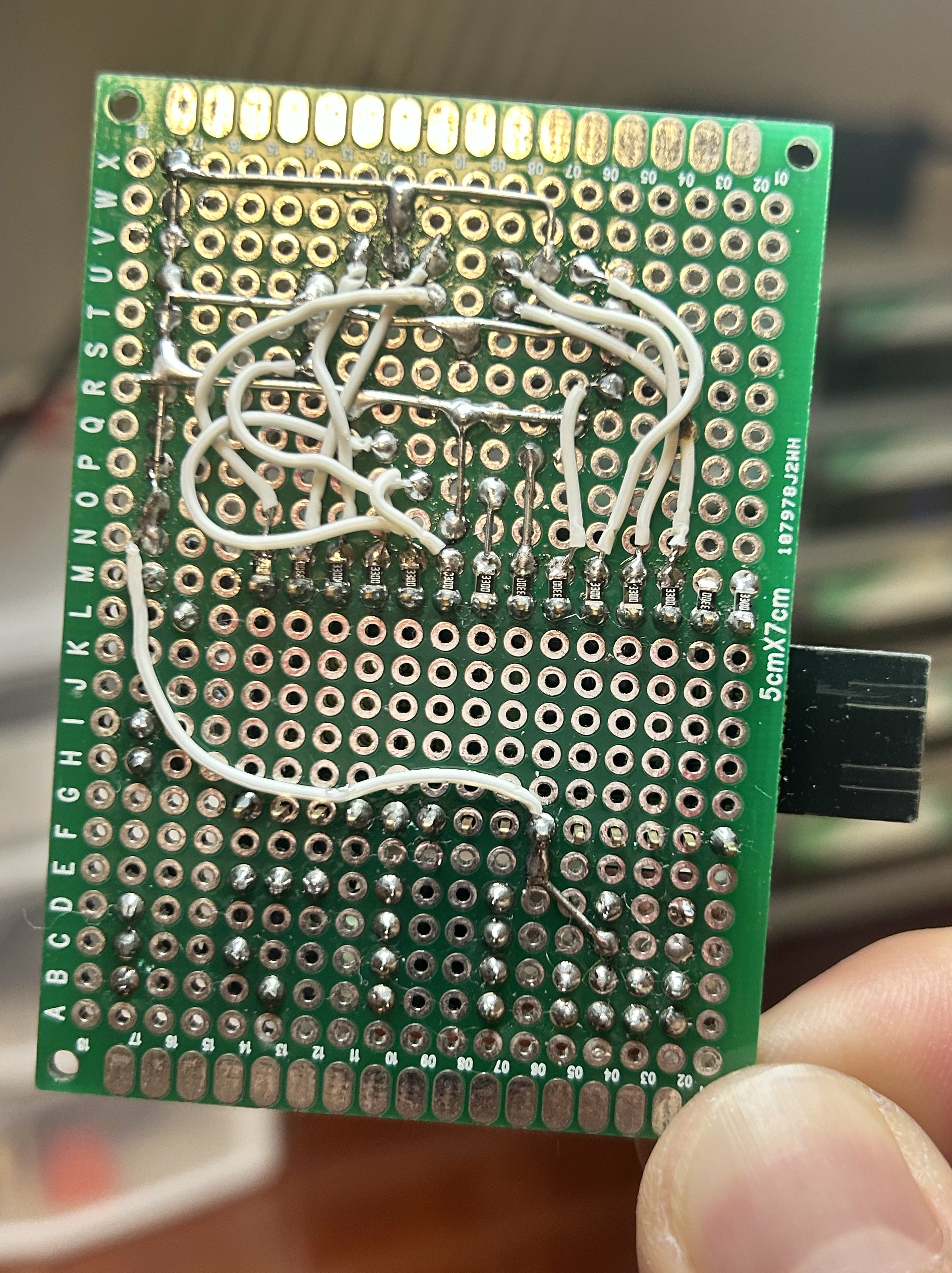
COVID-19 GENOME BLINKY
Early 2020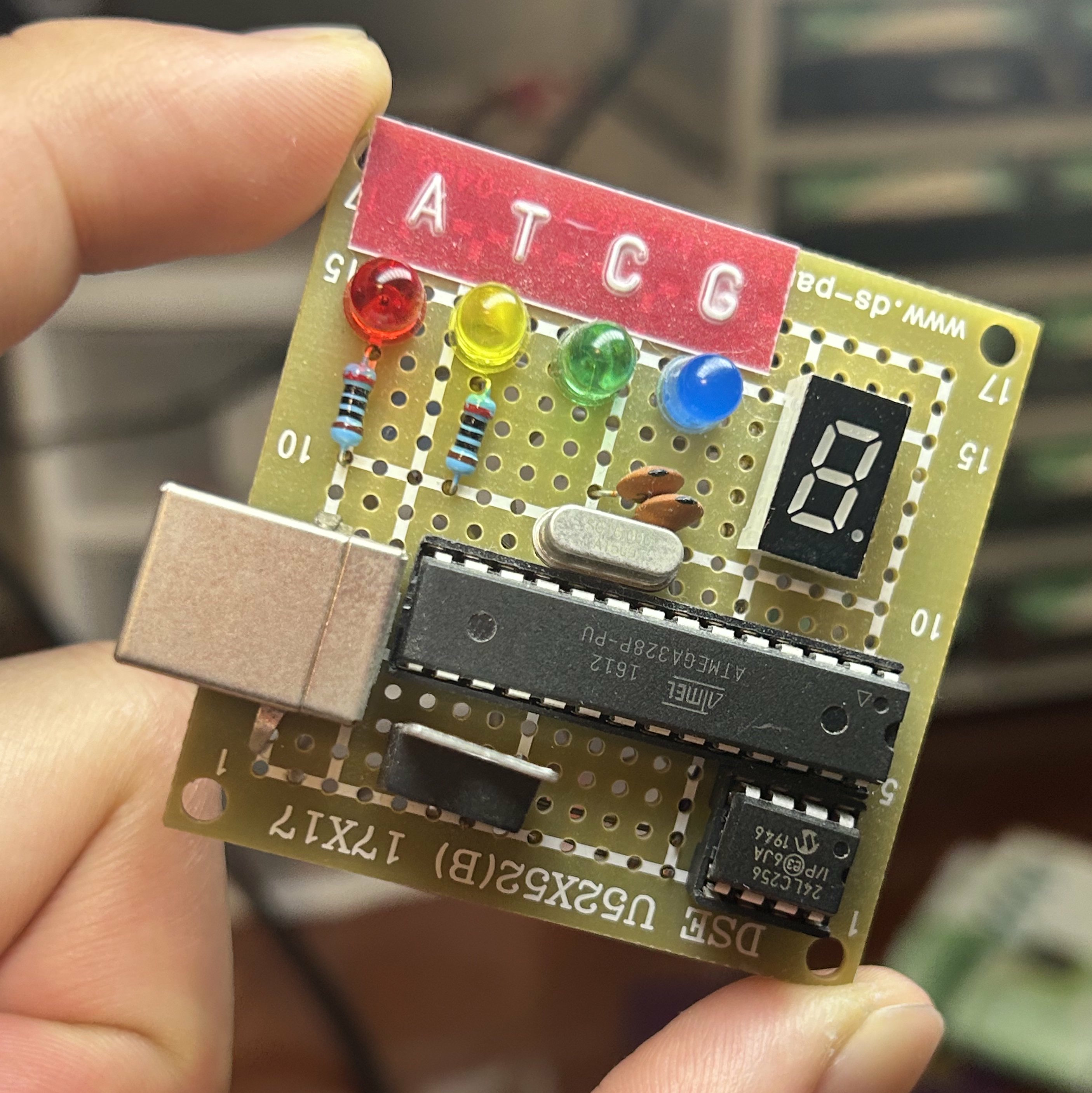
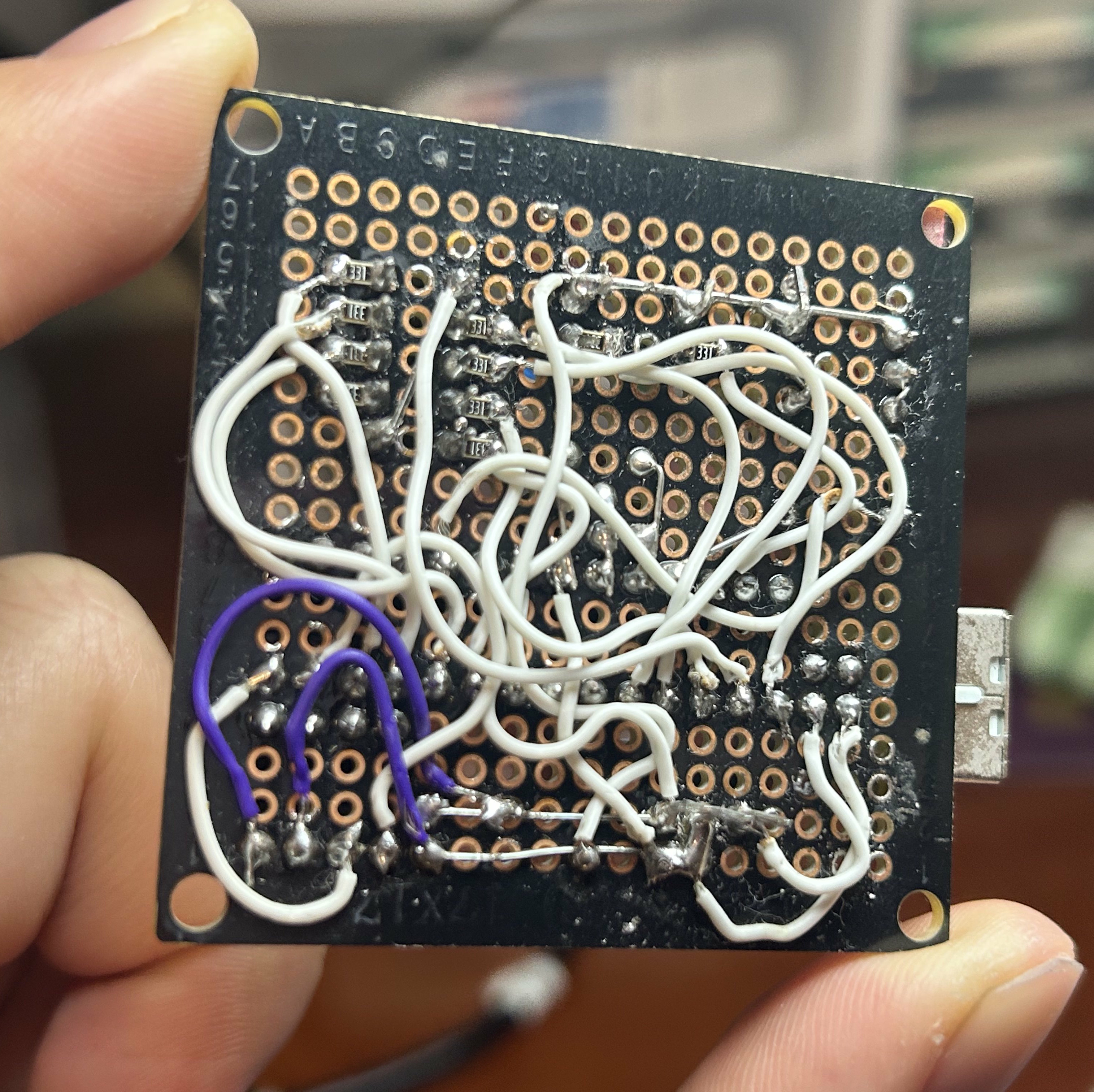
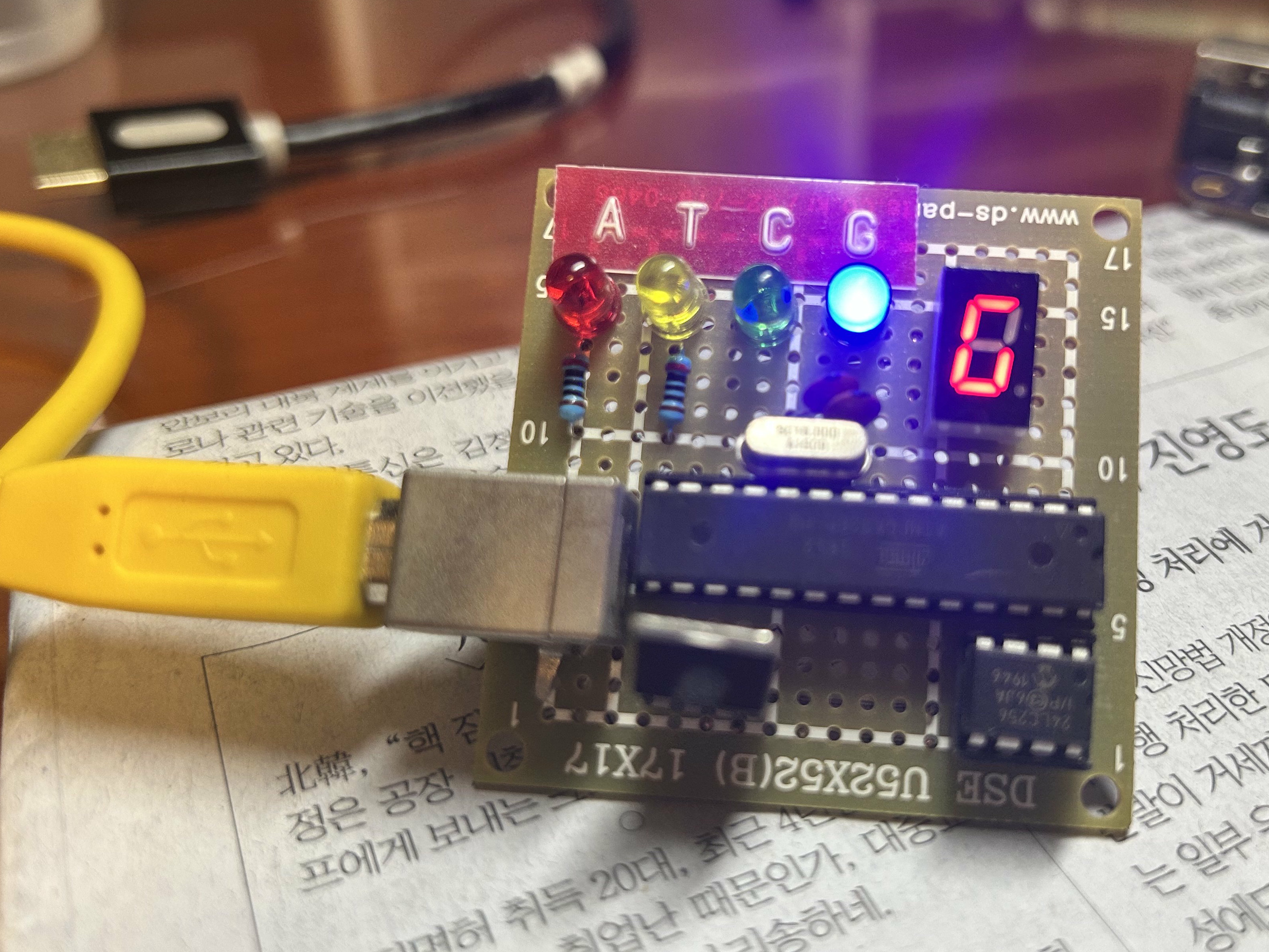
A little desk ornament I made for my dad's office (he's a doctor). An ATmega328P reads the nucleotide sequence of the Covid-19 virus from a 24LC256 EEPROM, and displays it on a bunch of LEDs. I made it during lockdown in early 2020, my final semester of high school. I was bored one night and couldn't fall asleep, so I made it in my room. I think it took about 4 hours.
I had to write a Python program to load the genome sequence onto the EEPROM. I think it took a text file of the nucleotides, and sent each character over to an Arduino over a USB-Serial link using PySerial, and the arduino would burn the bytes to incrementing addresses in the EEPROM.
I actually think this is one of my coolest projects to date, honestly. But I made it a long time ago and forgot most of the details, so here it is.
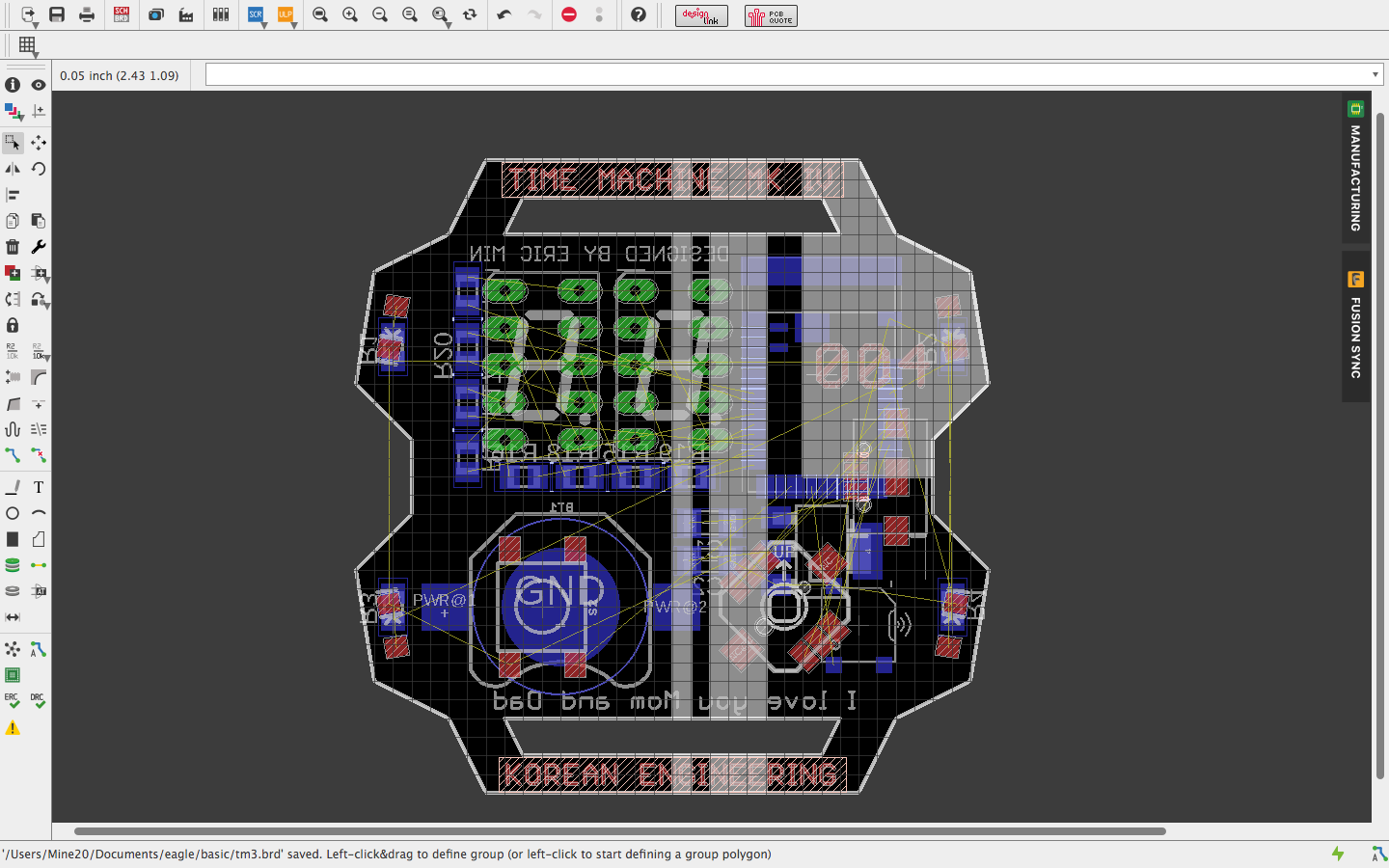
MINIMAL Z80 COMPUTER
Early 2022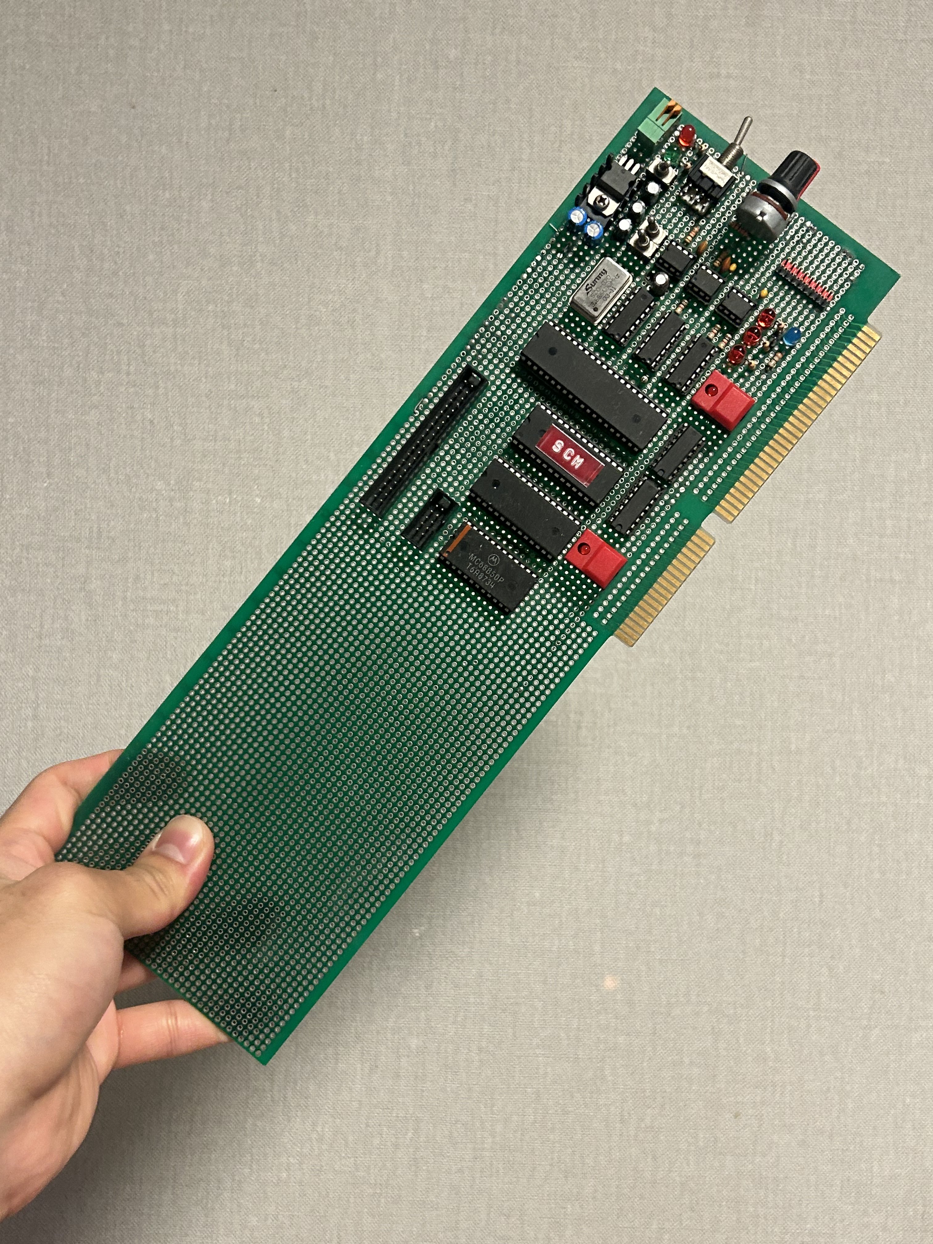
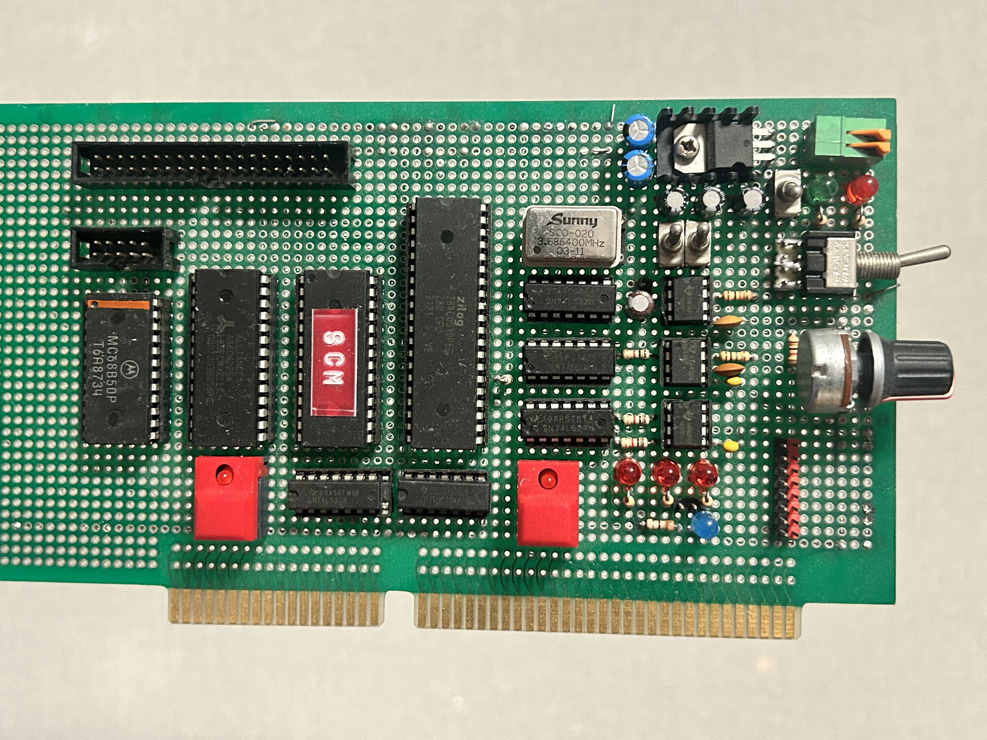
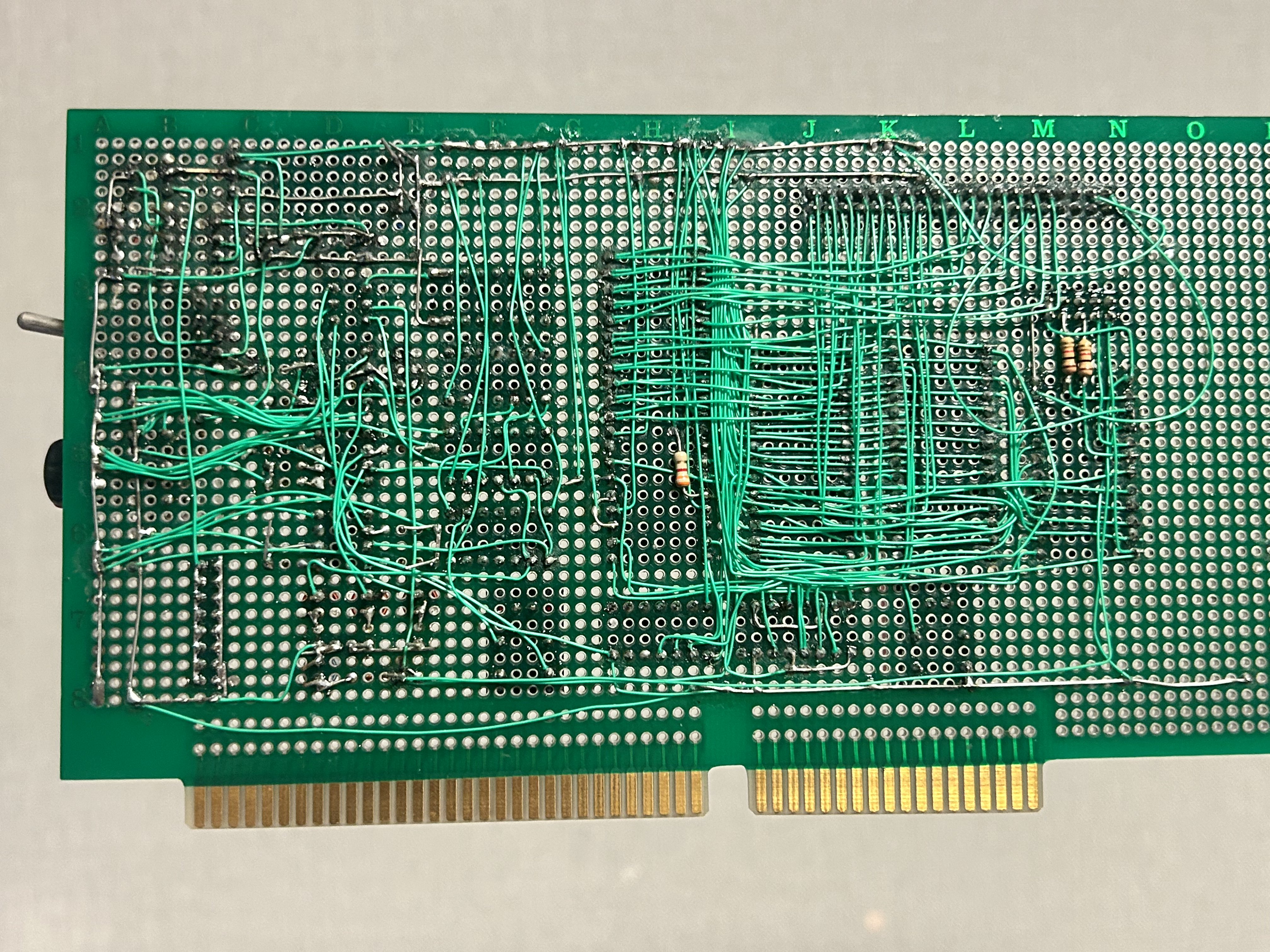
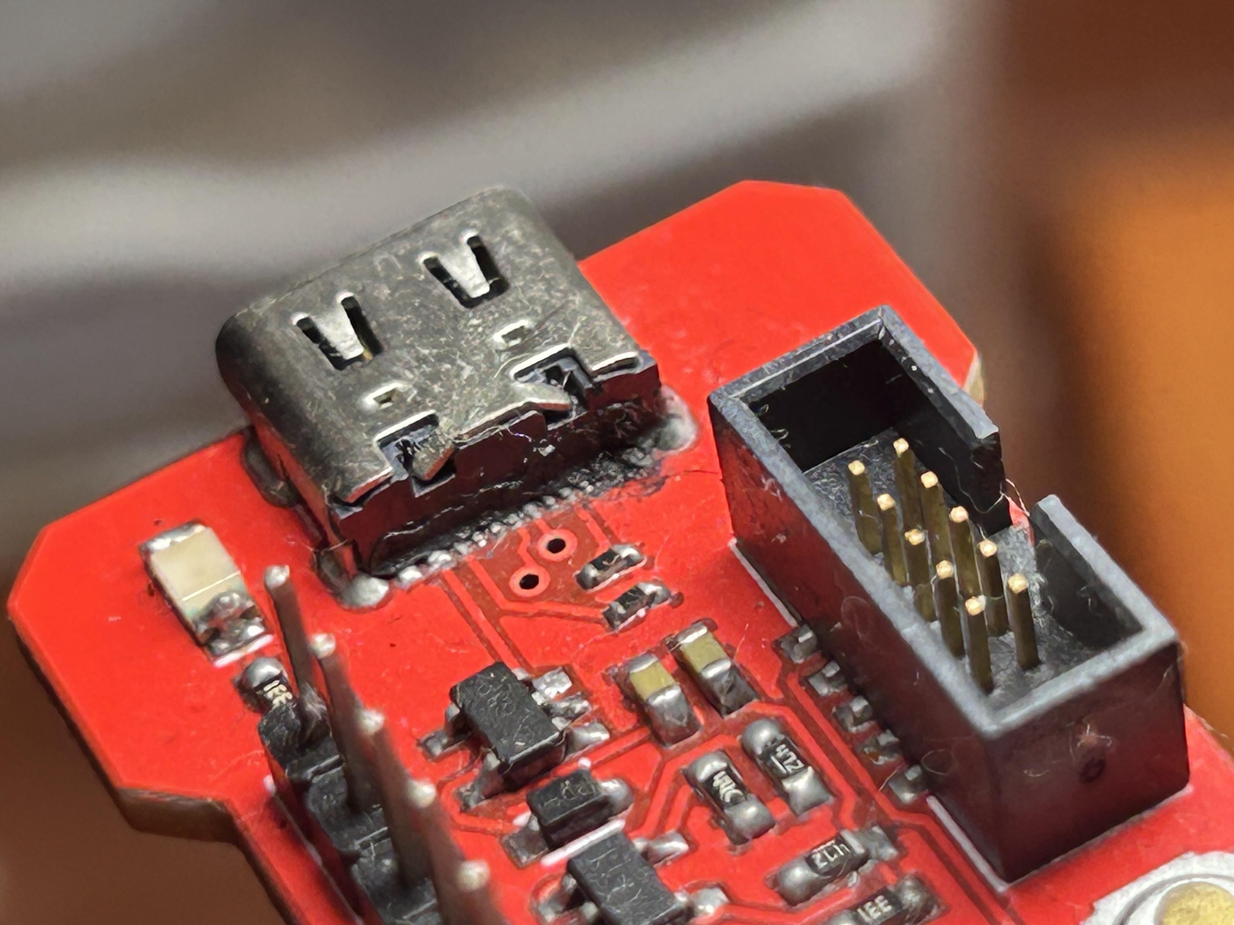
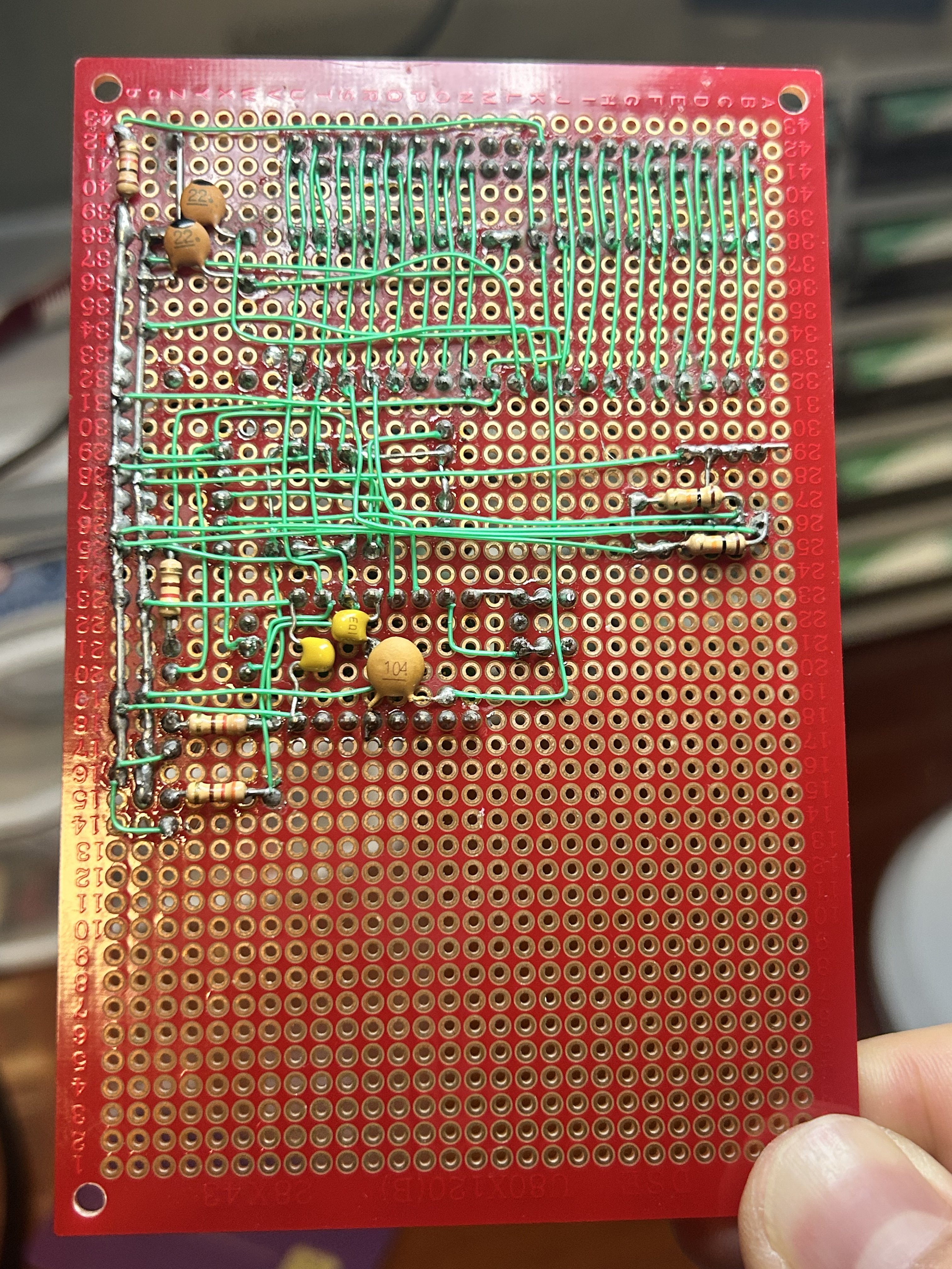
I made this during my first vacation when I was serving in the Korean army. I've been watching Ben Eater's excellent 6502 computer videos, and I was determined to build my own. I found Grant Searle's excellent minimal Z80 computer guide, so I decided to follow that, integrating Ben Eater's 555 timer clock circuit into it. So this is a minimal Z80 computer with I think 64K ROM, 32K RAM, and a variable clock with pause and single-step. On the photos you can actually see a ROM chip containing SCM plugged into the board. I believe the leftmost Motorola chip is a serial communication IC.
This was all built in a week. I remember most days I only slept maybe three hours. Maybe that's why it doesn't work. I checked connections, voltages, and continuity with a multimeter but wasn't able to find any faults. I definitely need to take another shot at it because this is way too good of a project to throw away.
The 40-pin header up top exposes the address bus, the data bus, and some control signals for me to connect to a microcontroller board, like an Arduino Mega, for me to use as a logic analyzer. I was sort of planning on making my own Z80 debugger as a side project to help with this project, but I eventually lost interest.
TIME MACHINE MK. 6
Mid 2020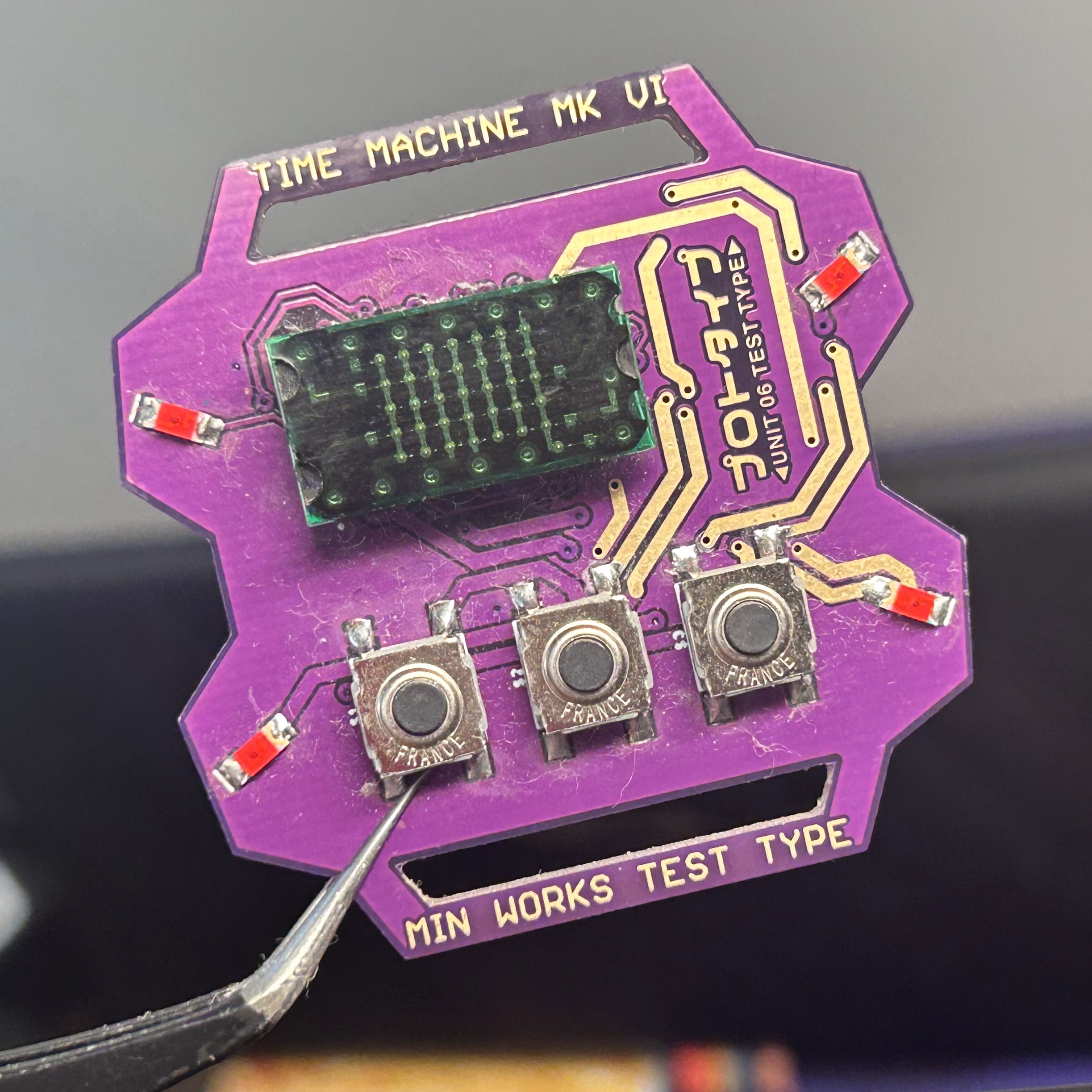
TM6 was a sorry attempt at a sort of graphical display. I had a bunch of LTP-305 dot matrix modules I bought a while ago to play with, that I never really put to use. I figured these would make a pretty sweet alphanumeric display, and I had an idea for a 3x5 fontset that could easily fit two characters into a single display module laid horizontally.
So I hastily made a new PCB. This was also around the time I started watching Neon Genesis Evangelion, so I decided to style TM6 in EVA Unit 01's colorscheme.
After I soldered the top side, I realized I forgot to put resistors at all for the LEDs. Now, looking at it now I think it would've been more or less fine without resistors. But this really killed my interest in the project, and I decided to give up on it. So the half-assembled one you see above is the only TM6 I have. I guess I never really had much commitment to the project to begin with, from how I ditched it so easily. Anyways, onwards to TM7.
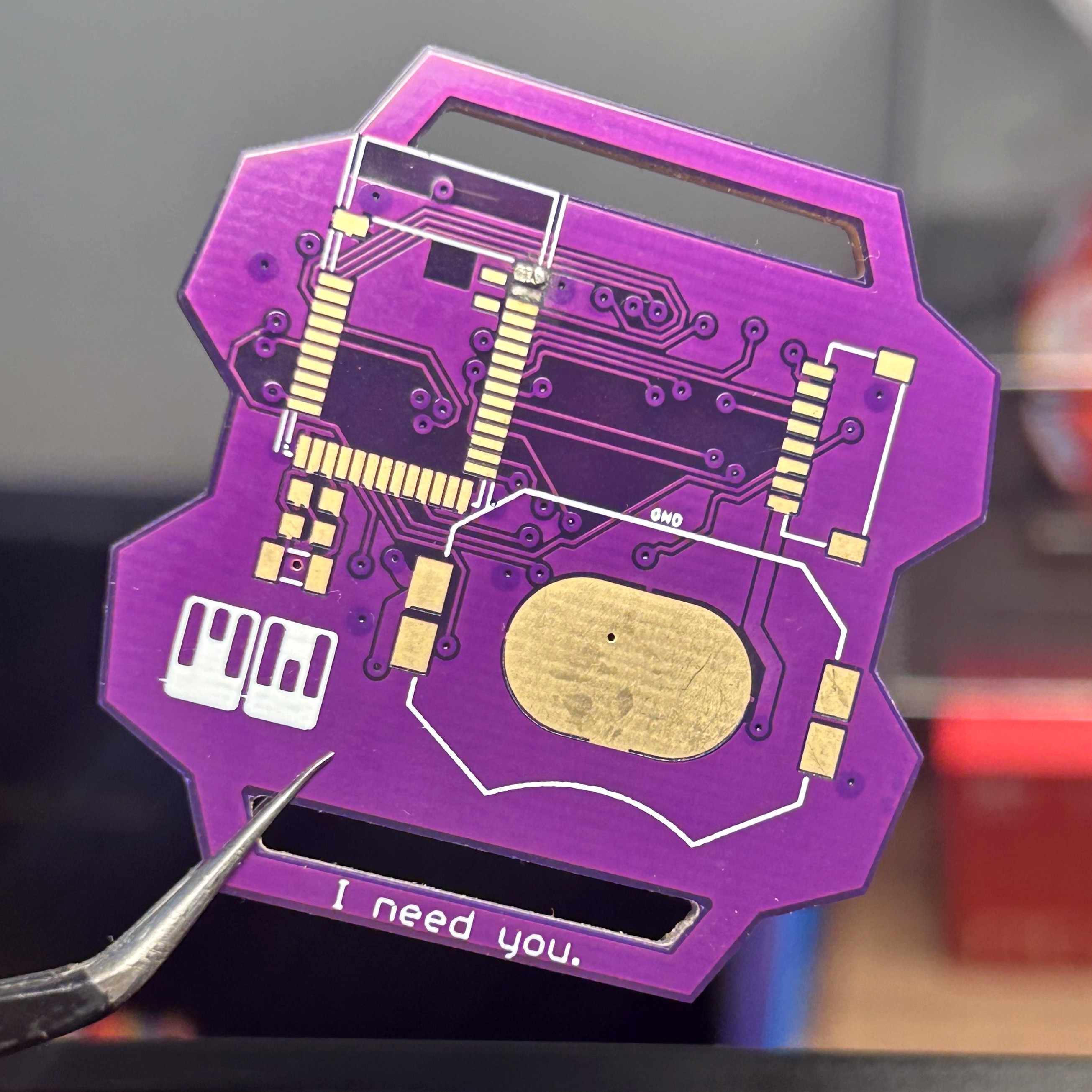
TIME MACHINE MK. 7
4/8/2023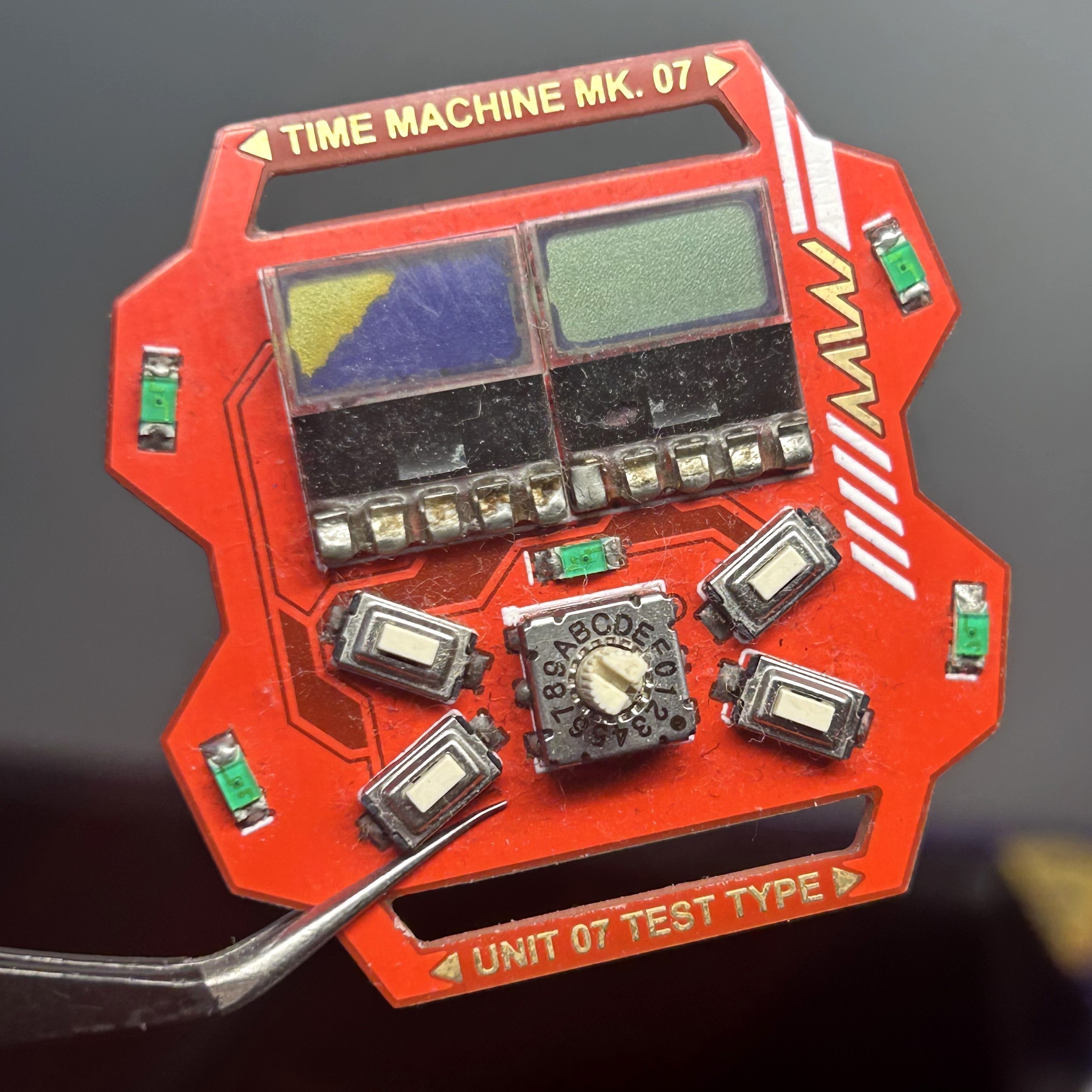
I started working on TM7 durign my time in the army, I think late 2022. I was still open to exploring new display options besides the 7-segment LEDs I had used for TM4 and TM5. After quite some digging, I found these tiny 4-digit 7-segment I2C LCD modules that would not only allow me to cram eight digits on the watch face, but also significantly kill battery life. So TM7's design sort of revolved around this new display.
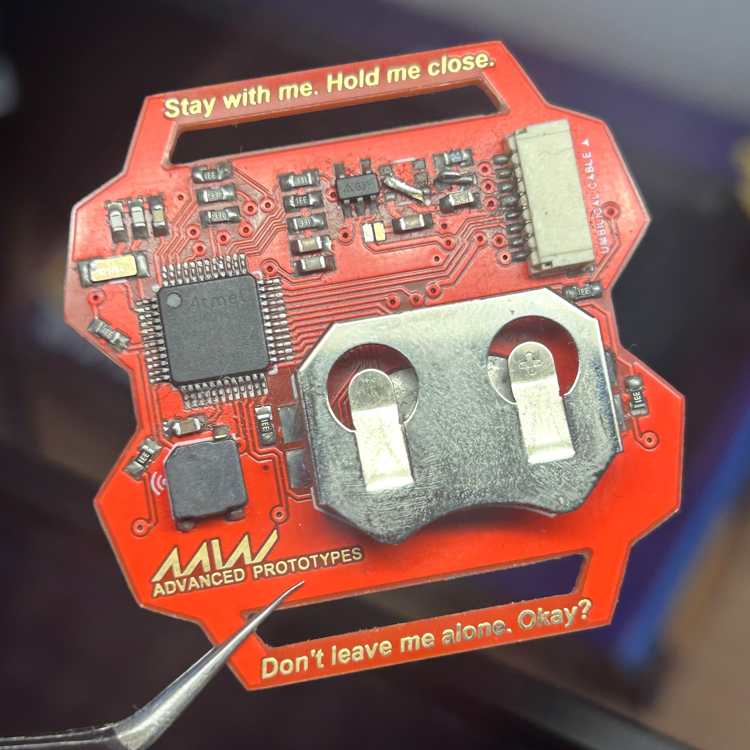
The PCB looks dead simple looking at it now, but this was going to be my most complex Time Machine yet, so I was very tentative on adding new features. So I made the stupid decision of making the power supply its own separate board, which would connect to TM7's "umbilical port", a JST-SH connector on the backside for both power and data transfer. I think I put the charging circuit on the umbilical interface, and only the LDO on TM7. I guess my logic was that if my battery charging circuit failed, I could just design a new umbilical interface and still keep TM7. But it didn't work like that and TM7 resulted a stillborn.
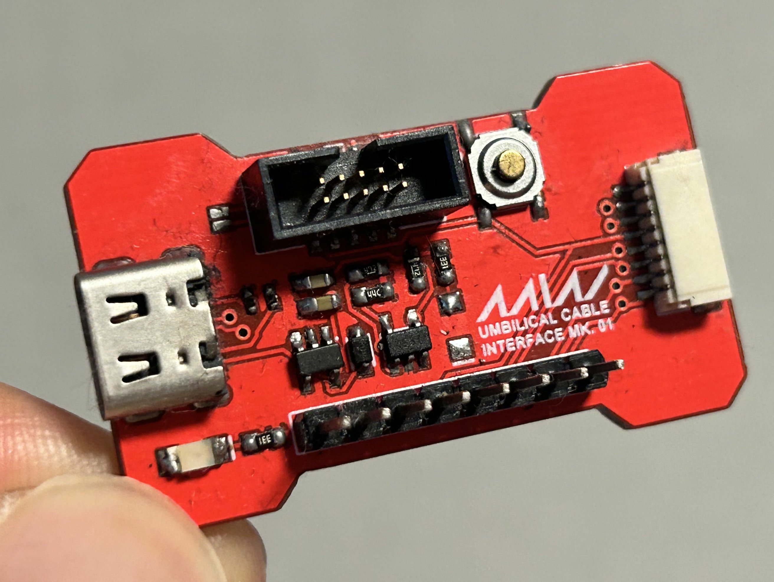
Not sure where the exact issue was, but I remember the umbilical interface got really hot once powered. So with the umbilical interface immediately dead, I tried to salvage what I can from TM7. I think the umbilical port gave access to SWD signals, but TM7 was unresponsive as well. Completely dead, no signs of life whatsoever. So I quickly started working on the next version. This time, I would grow a pair and stuff everything I can on the board without any funny ideas.
TM7 might've been a failure, but it was still the origin of many design elements and features seen on TM8. The all-new design, battery charging and load sharing circuit, and four-button layout all started here. Plus, TM7 was my first board fully routed by hand, which was a huge milestone in my "career".
STM32F4 BOARD
6/18/2021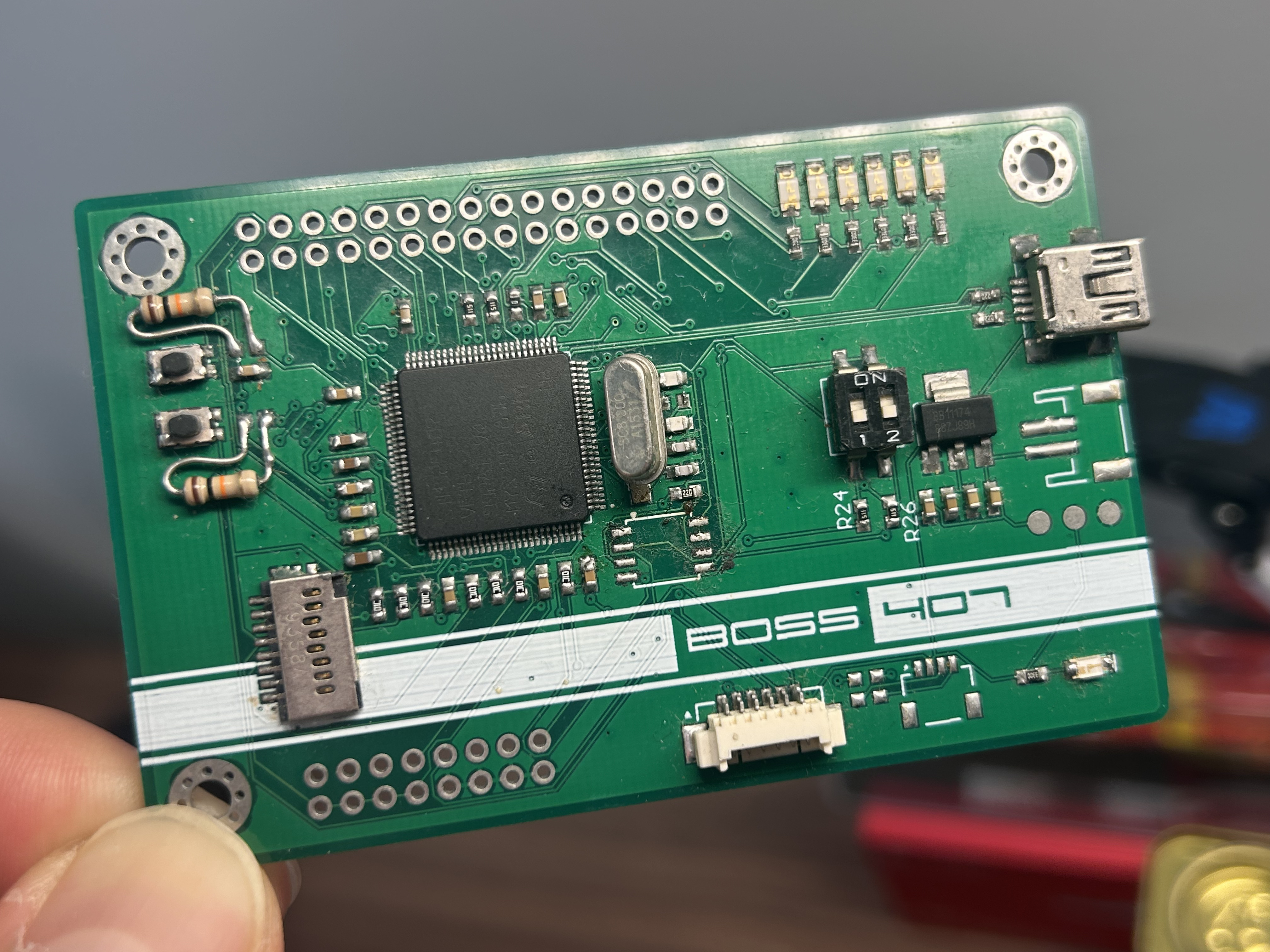
This was a little project to keep myself busy between finishing my freshman year of Purdue and my time in the army, my first shot at an STM32 board. You can immediately tell from the traces that this was entirely autorouted. Embarassing, I know. But this would be my last ever autorouted board.
There's really nothing special about this. I didn't even have a project in mind, I just wanted something faster than the AVR-based Arduinos I was used to by then. I figured making my own STM32 board would be a good learning exercise for later if I ever plan on needing a beefy microcontroller. And indeed it was, as this project gave me strong confidence to pursue C.R.A.M, an STm32F4 board I designed for Purdue's Formula Student team (it was never used on the car though).
C.R.A.M
1/12/2024Coming soon!!!
7-SEGMENT DECODER DESIGN
9/23/2022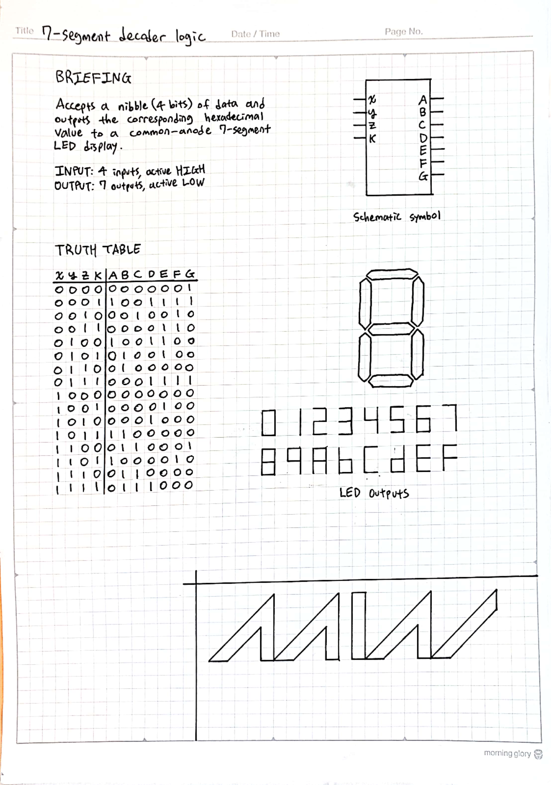
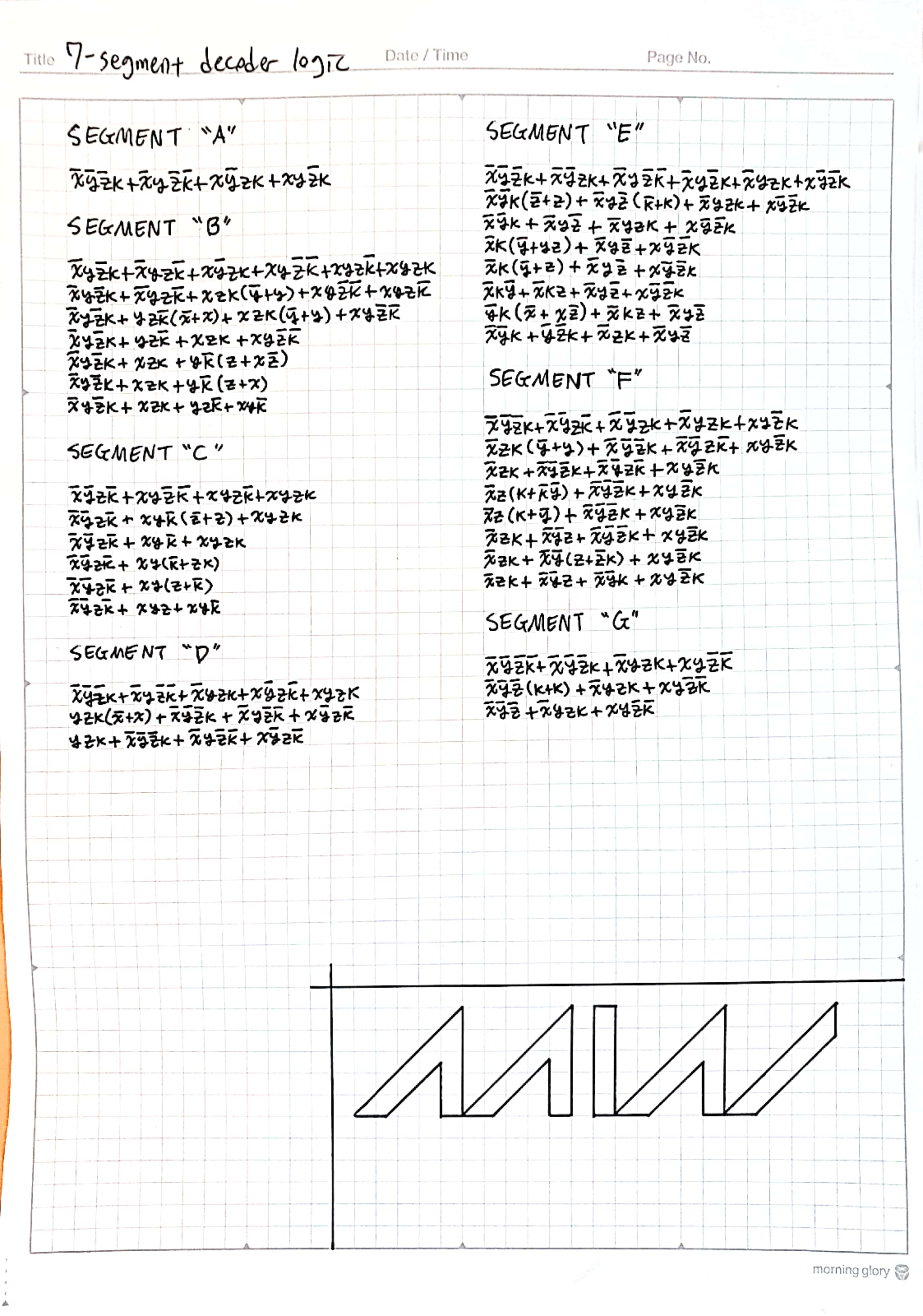
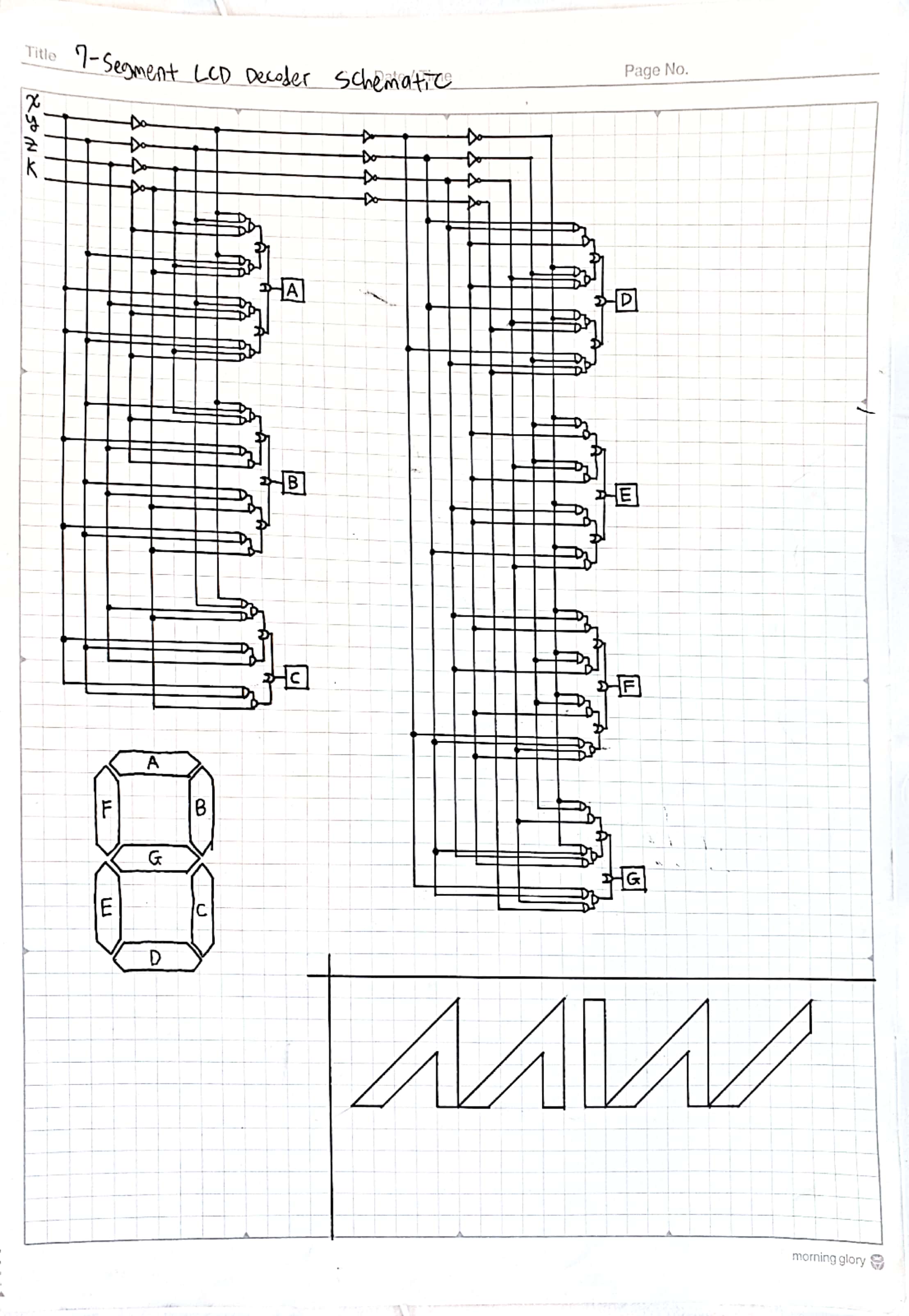
I was reading up on some basic boolean algebra when I was in the army. My service was right after freshman year of and I knew I was going to enter my first year as an Electrical Engineer following my service, so I figured it would be a good idea to get a little head start. As practice, I tried a hand at designing my own 7-segment decoder.
Years later, when I took my first FPGA course, I spend some free time in the lab implementing my design on an actual FPGA board. I don't quite remember the details but I remember several of the segments were off. In my defense, my design was only made with pen and paper, with only the correctness of my reductions checked with a computer.
GLOWING LED HEART
Early 2020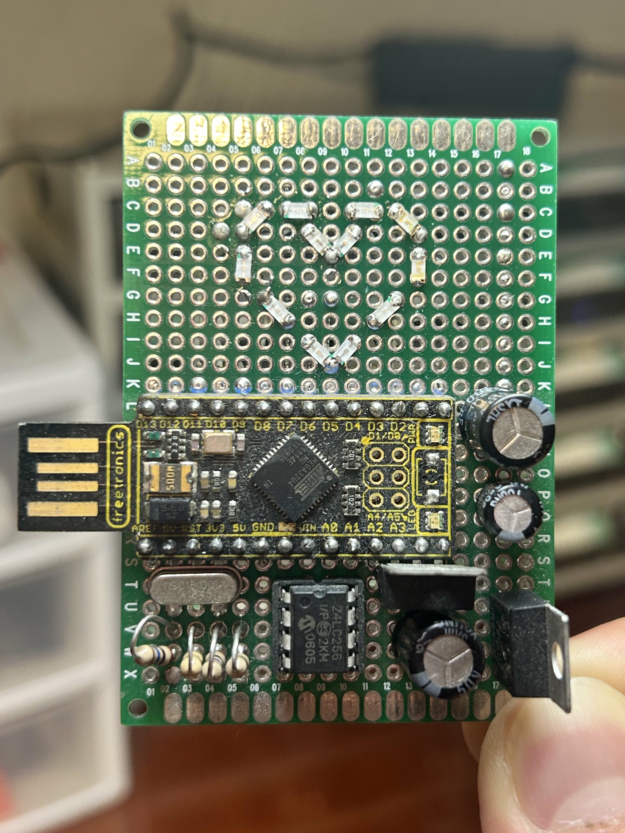
This was a small present I made for my parents for I think parents' day my last year of high school. It's just a bunch of LEDs wired to an ATmega32u4 board I had laying around and couldn't find a use for. The components on the bottom are just there to look cool. You can see they're not connected to anything on the backside!
The LEDs were really bright, so I made a little paper sheath to cover the top half of the device, and it did a pretty good job of killing the brightness while keeping the animation visible. You can see it in the video above.
COOKIE 2.0 ROBOTICS CONTROLLER
Mid 2017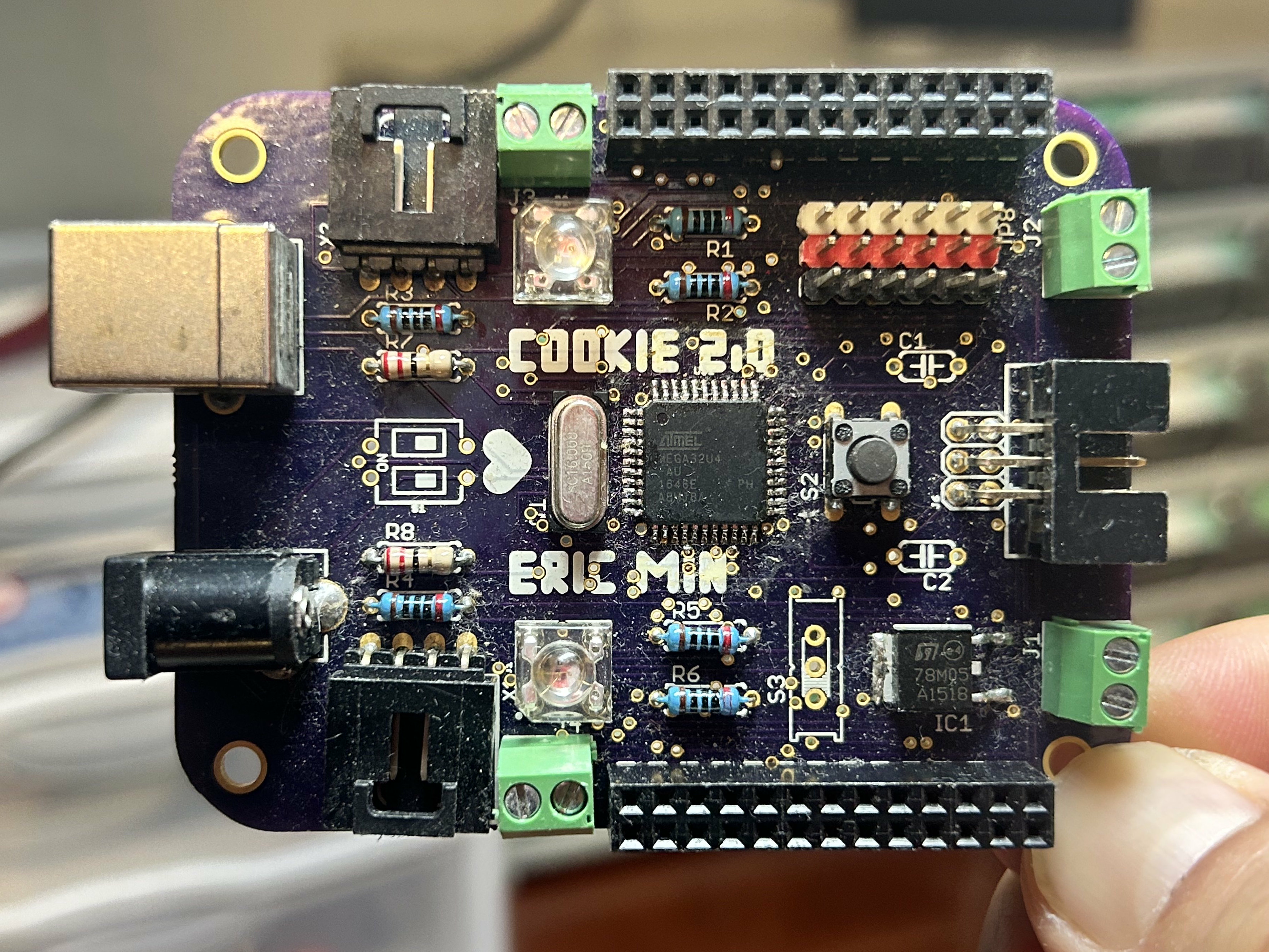
This was my first attempt at a "serious" PCB, a robotics-focused microcontroller board using an ATmega32u4. I made this I think at the end of my sophomore year of high school. It never worked.
The locking connectors you see on the sides are for I2C devices, and you can see I have dedicated connectors on the top for servo motors. Not sure what the screw terminal connectors were for, I can't quite remember.
I was actually planning on integrating a PCA9685 Servo driver on the PCB as well, but chickened out at the end because I wasn't confident enough to get the soldering done correctly. Well, I guess it wouldn't have mattered because it was dead on arrival.
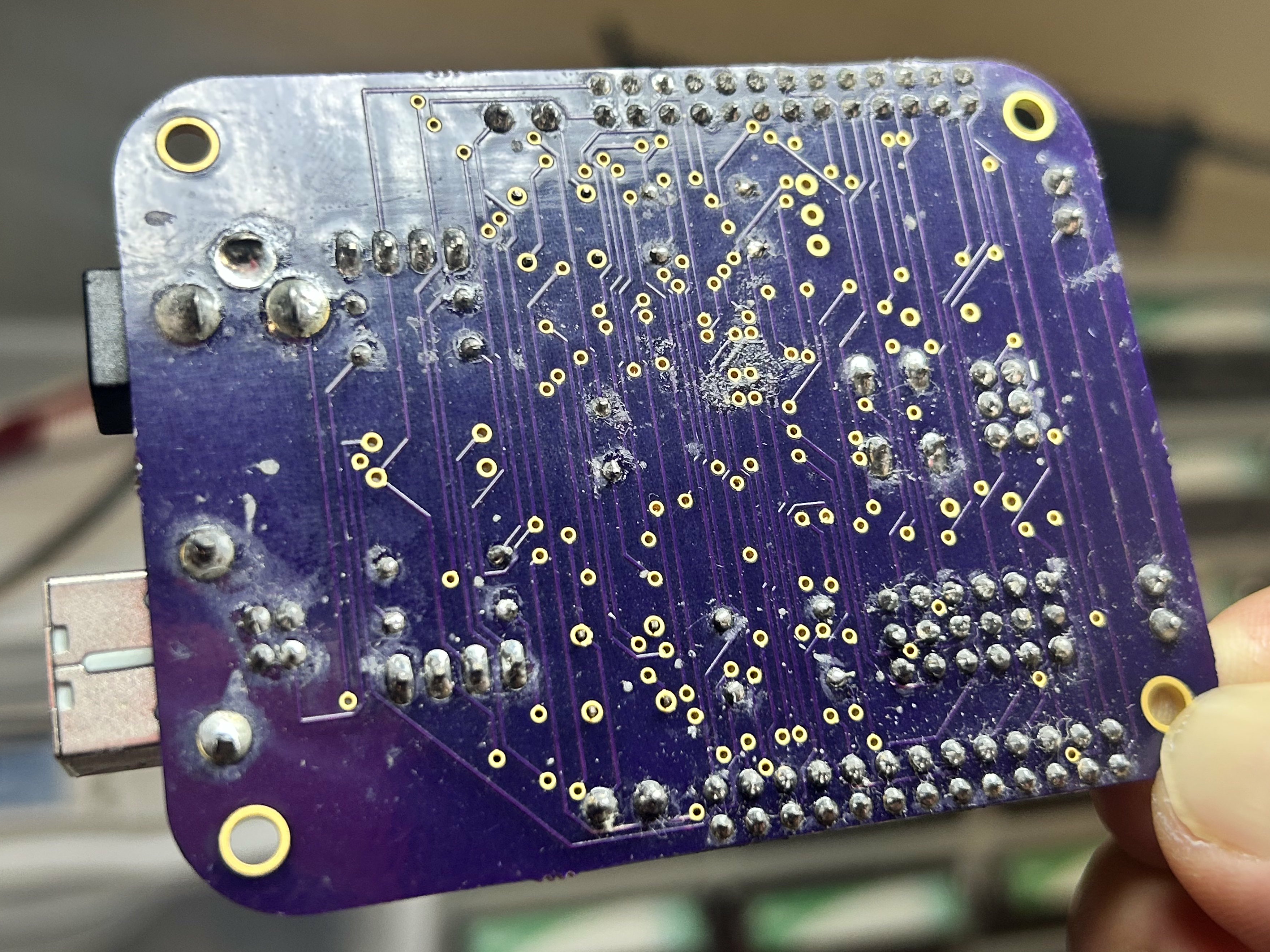
You can immediately tell by the backside traces that this was fully auto-routed. I only started hand-routing with Time Machine Mk. 8.
PARALLAX PROPELLER DEV BOARD
Mid 2022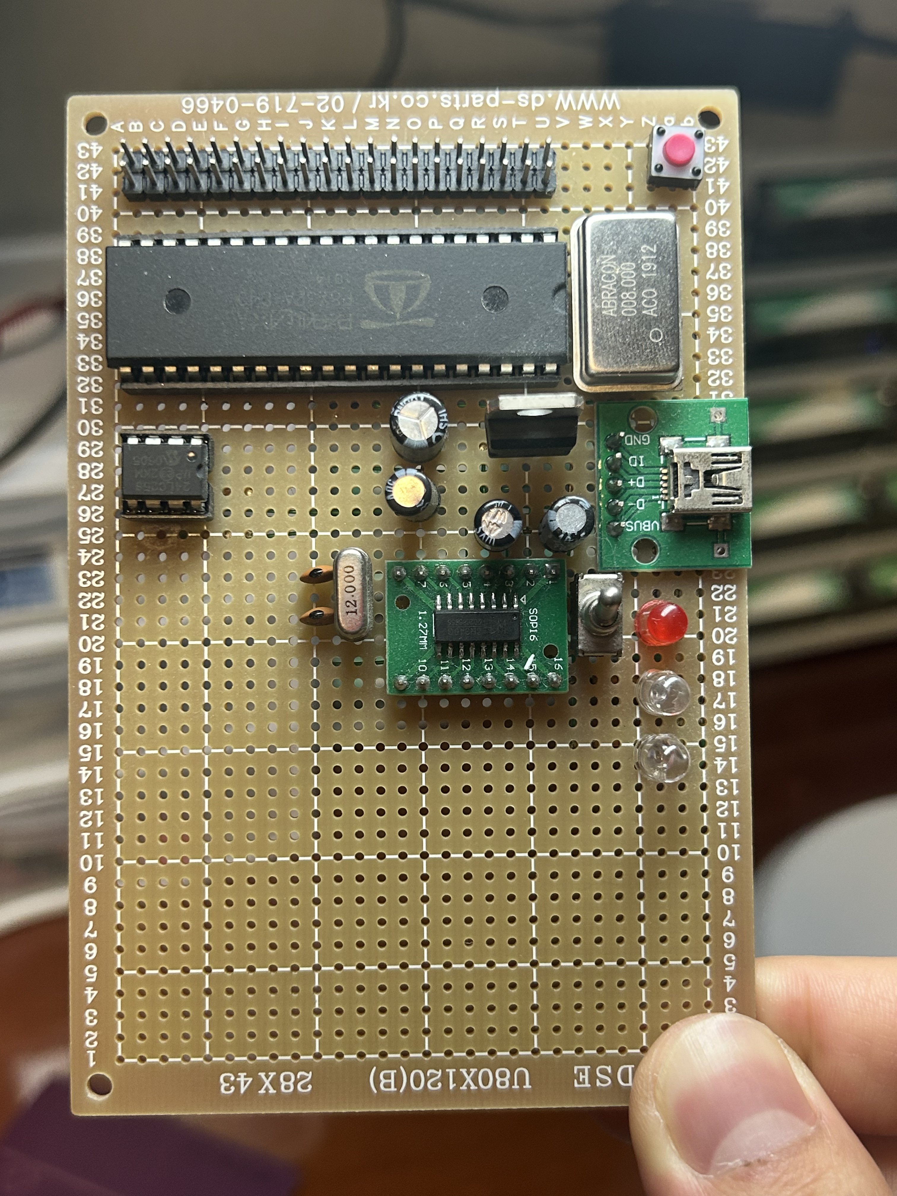
There was a brief period where I was kind of obsessed with the Parallax Propeller. An 8-core microcontroller available in a DIP package was wild to me. So naturally I made a dev kit for it. I remember learning a little bit of Spin and some Propeller-C, but never really did anything cool with this. I just blinked some LEDs and got bored quickly.
The board has The Propeller and its required EEPROM, along with an 8MHz clock, a USB-Serial converter, and two status LEDs.
Not to be mean, but I honestly can't believe how Parallax is still in business. Their Propeller 2 chip looks pretty sick, but with the exploding availablility of cheap ARM MCU/MPUs, I wonder if there are any legitimate users for it.
NRF52832 DEV BOARD
2/5/2020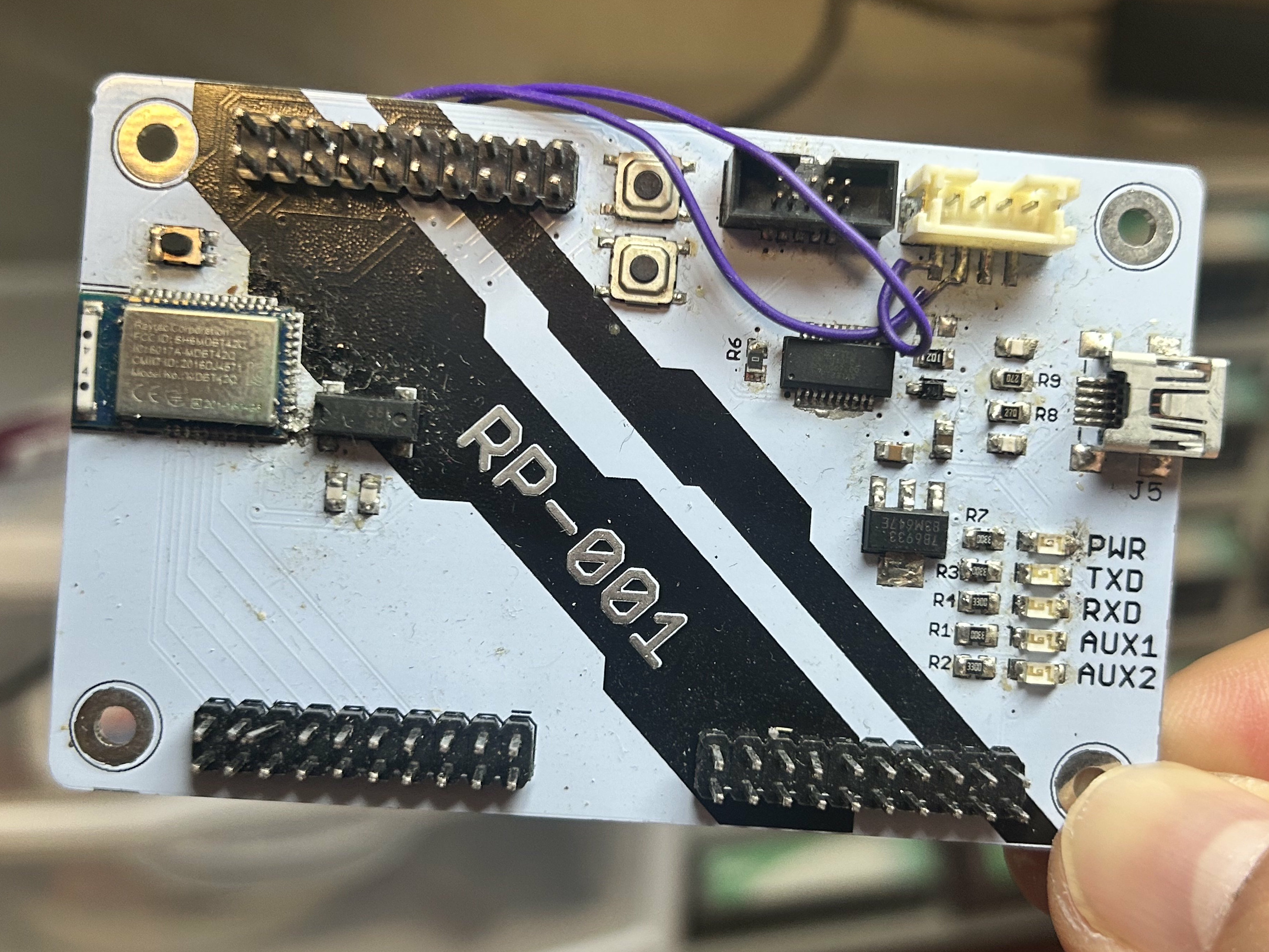
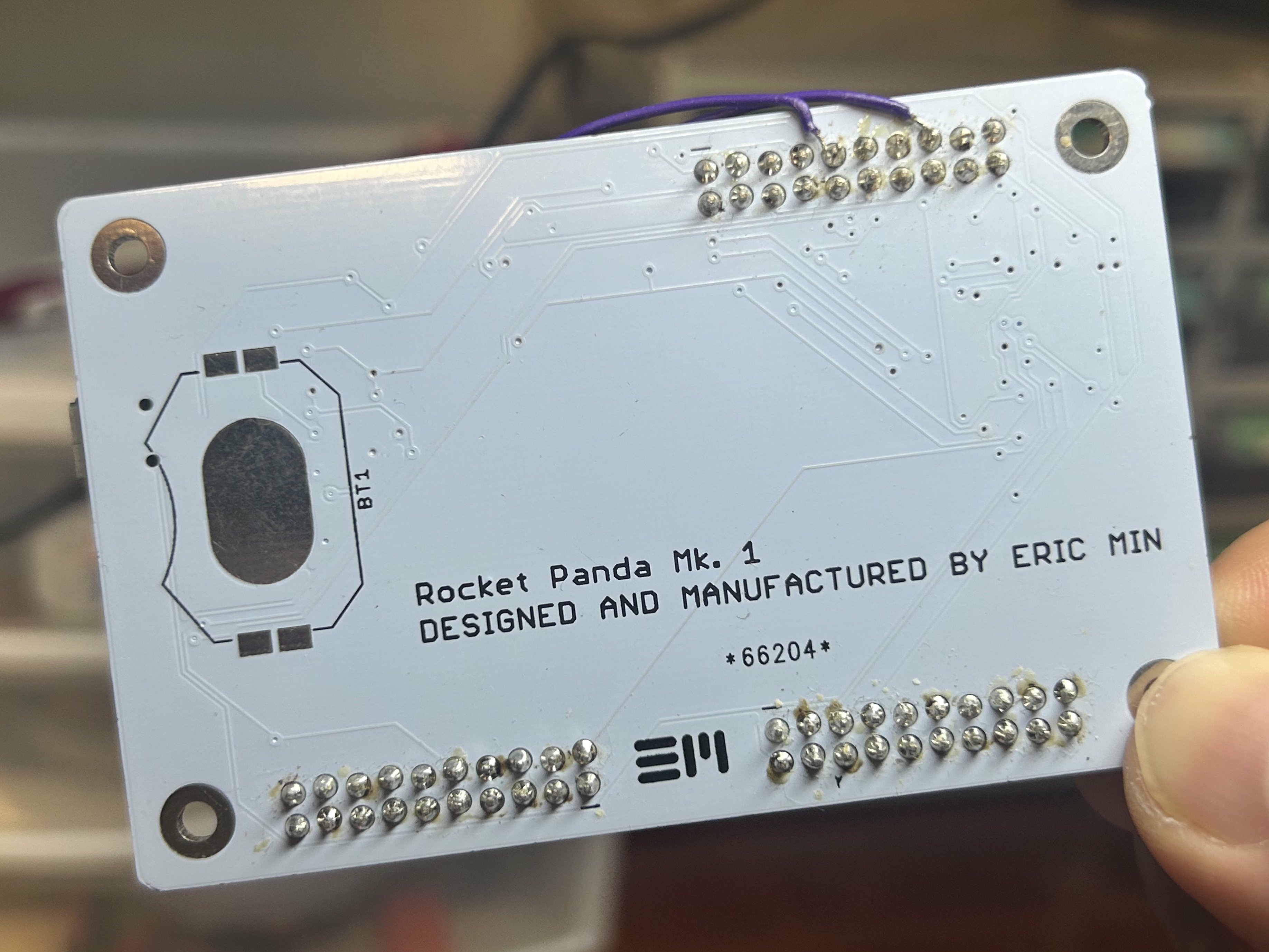
Made during my final semester of high school, this was another shot at a "serious" PCB project that came out stillborn. I remember spending quite a few hours trying to see what was wrong—I think I was able to get a debug probe to read and write to the NRF52 module using the Cortex debug port, but the USB-Serial connection was not working. I took a soldering iron to it one too many times and eventually burned the NRF52's pads past the point of recovery. Also, I'm not sure why I chose such a stupid name for the thing.
ATMEGA328P ROBOTICS CONTROLLER
Mid 2017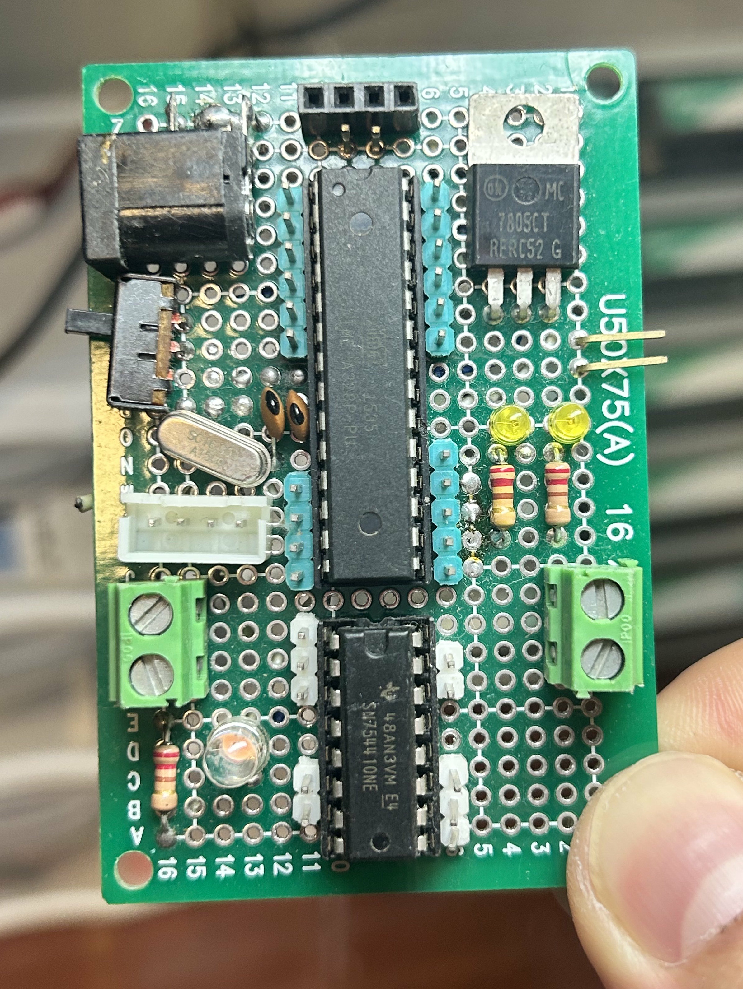
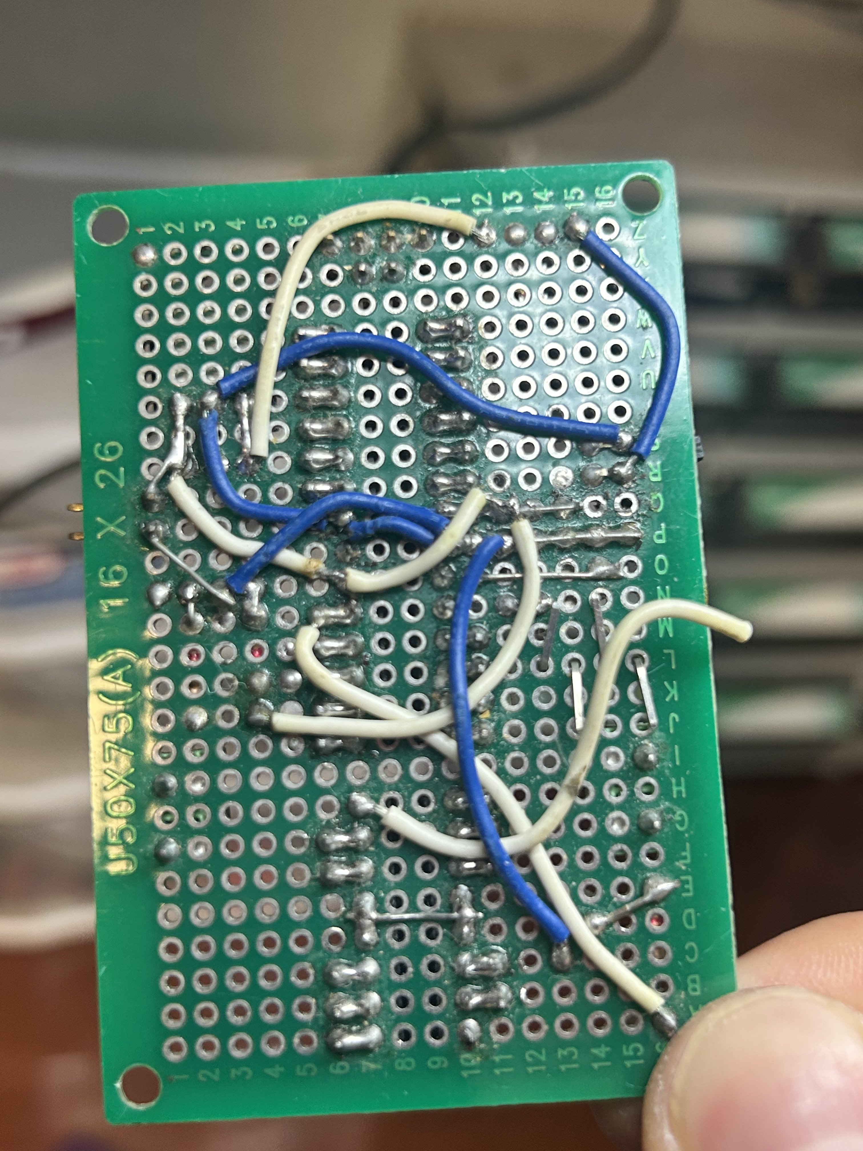
Another robotics controller. I think this was made before Cookie 2.0. I genuinely have no idea if this worked or not, I'm not sure if it was even finished to working order looking at the photos now. But it used an ATmega328P along with an SN754410 H-Driver IC. I think I just blindly followed a schematic online without really knowing what I was doing. Anyways, here it is.
CUSTOM GAMEBOY DMG
3/14/2020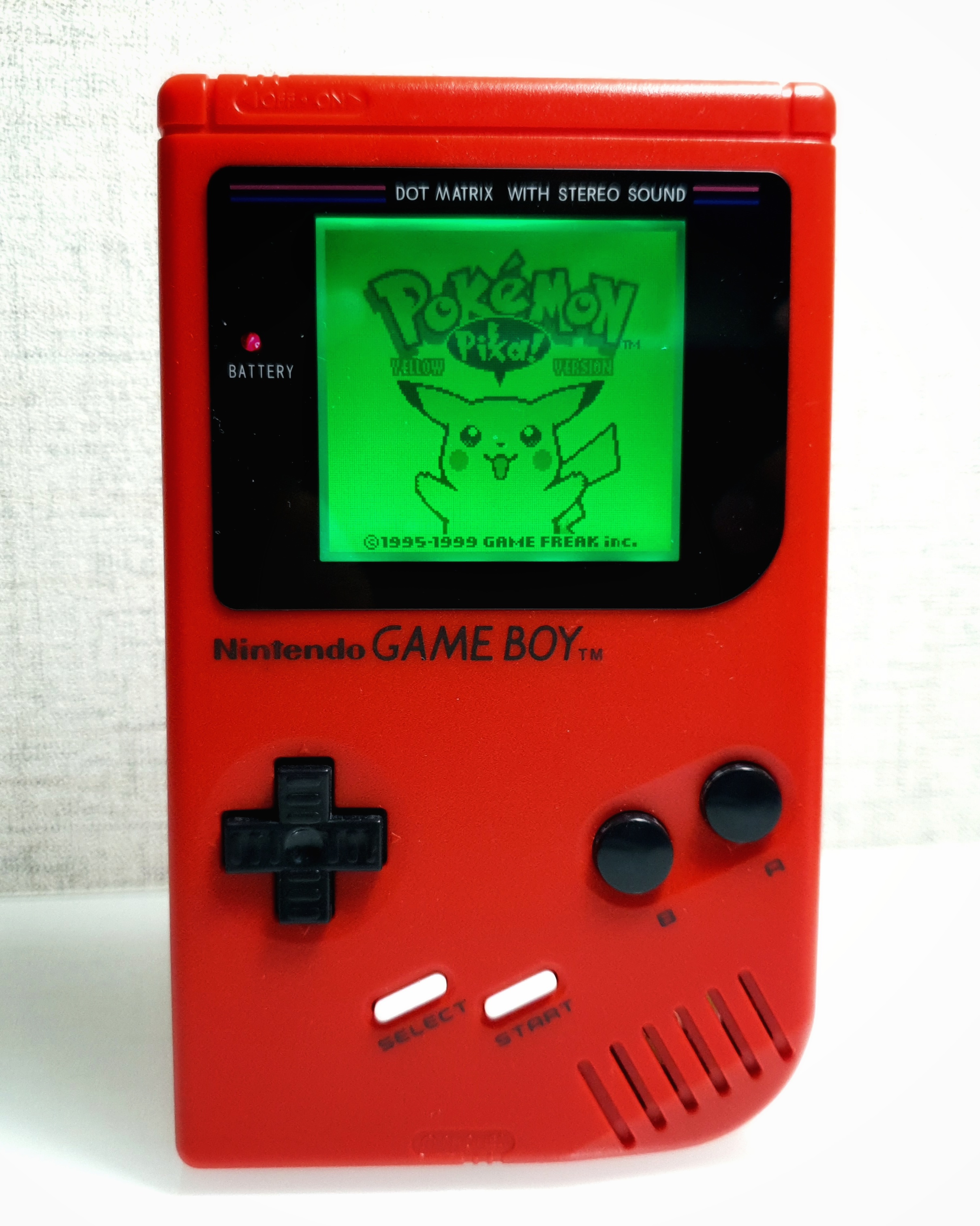
(The following content was copy-pasted from what used to be its own article)
During the summer of 2019, my family and I went on a short two-day trip to Akihabara, Japan. I was lucky enough to visit Super Potato, a local retro gaming store. There, I bought a red Play it Loud edition DMG gameboy. Inspired by Kaneda's bike from Akira, I decided to turn it into a custom DMG with custom coloring and a backlit/biverted screen. This was my first ever gameboy mod so I didn't bother to document my process. Overall, it took me over two hours.
Red is one of my favorite colors and I think it looks dope on my console. The black and white buttons are the icing on the cake. Of course, my favorite part is the green backlight and biverted screen. It is crispy and clear while also being easy on the eyes. The photo doesn't do it justice, it looks amazing in real life. The green color goes well with the red shell and the entire console oozes Akira vibes, just like how I wanted it to be!